
LM324 Based LED VU-Meter
The eight LED audio level meter circuit serves as a visual representation of audio signal levels, providing real-time feedback on the amplitude of audio inputs. The use of two low-power quad op-amps, specifically the LM324, allows for efficient signal processing while minimizing power consumption.
The circuit typically operates by receiving an audio signal, which is then amplified and processed by the op-amps. The output from the op-amps controls the illumination of the LEDs, where each LED corresponds to a specific range of signal levels. This arrangement enables the user to easily monitor audio levels, ensuring optimal performance and preventing distortion.
In this design, the op-amps are configured in a way that allows for a precise response to varying audio levels. The first stage may involve signal conditioning, such as filtering and amplification, to prepare the audio signal for further processing. The second stage utilizes the quad op-amps to compare the processed signal against predefined thresholds, which are set to activate the corresponding LEDs.
The LM324 op-amp is particularly advantageous due to its low power consumption and ability to operate over a wide voltage range, making it suitable for battery-operated devices. The circuit design may also include resistors and capacitors to set the gain of the op-amps and to stabilize the output, ensuring that the LEDs respond accurately to the audio signal.
Overall, this circuit design is effective for applications where audio level monitoring is essential, such as in mixing consoles, audio interfaces, and sound reinforcement systems. The implementation of the LM324 op-amps in conjunction with the LED indicators provides a reliable and efficient solution for visual audio level monitoring.The circuit was conventionally designed with eight LED audio level meter made out of two low power quad op-amps which utilizes LM324. Volume Unit . 🔗 External reference
Related Circuits

Transmitter RF Output LED Indicator Circuit Diagram. This RF output detector circuit, which includes a visual indicator, can be useful for an RF application. The transmitter RF output LED indicator circuit is designed to provide a visual representation of the...
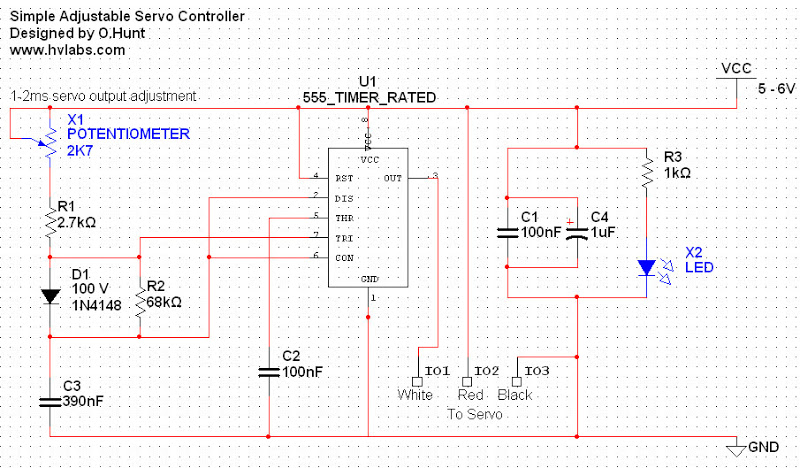
Servos are valuable components for various applications, including robotics, automation, and remote control tasks, such as steering model vehicles. They are relatively inexpensive and readily available; however, controlling them can be somewhat challenging as they require specific timing to...
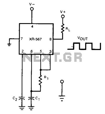
The frequency of the current-controlled oscillator can be doubled by feeding a portion of the square-wave output from pin 5 back to the input at pin 3. This configuration allows the quadrature detector to operate as a frequency doubler,...
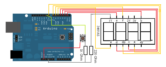
The 7-segment LED display is a highly useful component, yet it can be quite confusing and challenging for beginners to use. However, it becomes straightforward once it is operational for the first time. The display consists of seven LEDs,...
An LED flasher circuit can be constructed using a 555 integrated circuit (IC). The use of the 555 IC allows for greater flexibility in adjusting the flashing rate of the LED. This LED flasher circuit is similar to other...
PIC C Compilers are utilized to compile source code, leveraging the extensive built-in functions offered by these compilers. A single C statement can produce multiple pages of PIC RISC instructions, eliminating the need for manual coding. CCS charges $125...