
VU meter circuit
Part List
R1=10Kohm for 4ohm R3=390ohm D1-10=LED
R1=18ohm for 8ohm R4=2.7Kohm S1=mini switch
R2=10Kohm C1=2.2uF 25V IC1=LM3915
The described circuit functions as a power level indicator for a power amplifier, providing visual feedback on the output signal level. It is designed to operate in parallel with the amplifier's output, allowing for accurate signal monitoring without interfering with the amplifier's performance.
The circuit utilizes a variable resistor, R1, which is adjusted based on the impedance of the connected loudspeaker. Two values for R1 are provided: 10 kΩ for a 4-ohm load and 18 ohm for an 8-ohm load. This adaptability ensures that the circuit can accurately reflect the power level across different speaker impedances.
The input signal from the power amplifier is fed into the circuit, where it is conditioned by the resistors R2 and R3. R2, with a value of 10 kΩ, helps to set the input impedance of the circuit, while R3, valued at 390 ohms, is used for current limiting, protecting the subsequent components from excessive current.
The output signal is processed by the LM3915 integrated circuit (IC1), which is a LED bar graph/LED dot display driver. This IC converts the analog input voltage into a corresponding visual output on a series of LEDs (D1-10). The LM3915 can be configured to operate in either bar graph or dot mode, providing flexibility in how the output is displayed.
Capacitor C1, rated at 2.2 µF and 25V, is included to filter any high-frequency noise from the power amplifier, ensuring that only the intended signal levels are displayed.
A mini switch (S1) is also included in the design, allowing for easy on/off control of the circuit, enhancing usability and convenience.
Overall, this circuit is a practical solution for monitoring power amplifier output levels, with adjustable parameters to accommodate various speaker configurations and a clear visual indication of power levels through LED display.The circuit is placed parallel with the exit of power amplifier and us gives the level of signal ,from output. Changing resistance R1, in the input circuit, we adapt the indication of power, in the resistance of loudspeaker, that we use.
Part List R1=10Kohm for 4ohm R3=390ohm D1-10=LED R1=18ohm for 8ohm R4=2.7Kohm S1=mini switch R2=10Kohm C1=2.2uF 25V IC1=LM3915 🔗 External reference
Related Circuits
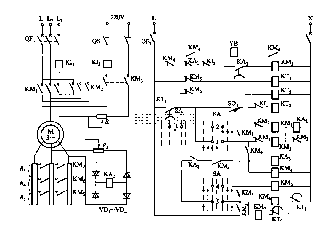
Figure 3173 illustrates a control circuit for a wound rotor induction motor that enables mechanical braking, dynamic braking, and reverse braking functions. The circuit includes various components such as relays, contactors, and time relays to manage the motor's speed...
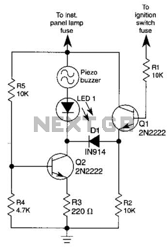
The base of Q1 is connected to the car's ignition circuit; the easiest point to make that connection is at the ignition switch fuse in the car's fuse panel. Also, one side of the piezoelectric buzzer is connected to...
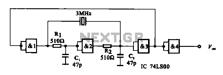
A crystal oscillator circuit is composed of several gates. Figure (A) illustrates a crystal oscillator circuit operating at 1 MHz, while Figure (B) depicts a 20 MHz crystal oscillator circuit. Figure (C) represents a variable crystal oscillator circuit with...
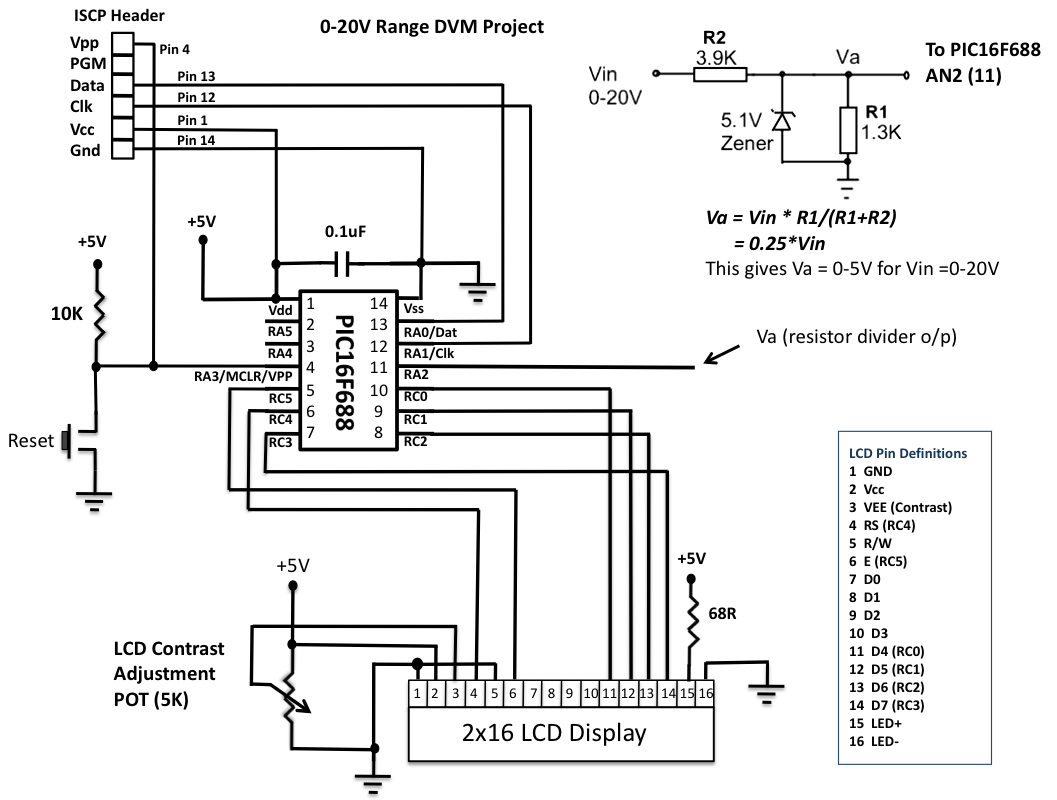
This is another version of an older digital voltmeter (DVM) project that was based on the PIC12F683 microcontroller. The previous version displayed the measured voltage on an LCD driven serially by the PIC12F683 using three I/O pins. The new...
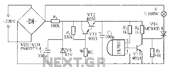
The H1.9811 single-channel flash control integrated circuit from Wuxi Love Core Microelectronics Co., Ltd. is designed for controlling flashing warning lights in road barricades. It features an integrated internal RC oscillator, frequency divider, output buffer amplifier, shaping circuit, and...
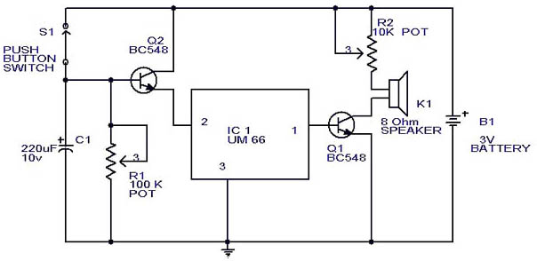
This circuit is a slight modification of a previous design. In the earlier version, the switch needed to be held down for the entire duration of the music playback. In this updated circuit, pressing the push button once charges...