
E crystal oscillator circuit composed of several gates

The crystal oscillator circuit is a fundamental component in various electronic applications, providing a stable frequency reference for timing and frequency generation. The design typically includes multiple logic gates, which serve to amplify and shape the oscillation signal produced by the crystal.
In the circuit operating at 1 MHz (Figure A), the crystal's resonant frequency is achieved through a feedback loop involving several gates. The configuration ensures that the output frequency remains stable and precise, suitable for applications such as clock generation in digital circuits.
The 20 MHz crystal oscillator circuit (Figure B) functions similarly but is designed to operate at a higher frequency. This circuit may utilize a different crystal type or additional circuitry to accommodate the increased frequency while maintaining stability and low phase noise.
The variable crystal oscillator circuit (Figure C) offers tunability across a range of 2-20 MHz, allowing for frequency adjustments to meet specific application requirements. This is typically achieved through the inclusion of variable capacitors or inductors in the feedback path, enabling fine-tuning of the oscillation frequency.
The variable oscillator circuit diagram in Figure D illustrates a design that can operate within the 5-10 MHz range. This may involve a combination of fixed and variable components, allowing for a balance between stability and flexibility in frequency selection.
Lastly, the dual-loop crystal oscillator circuit (Figure E) employs two feedback loops to enhance performance characteristics such as frequency stability and phase noise reduction. This design is particularly useful in high-precision applications where maintaining a consistent output frequency is critical.
Overall, crystal oscillator circuits are essential for providing reliable frequency references in various electronic systems, with different configurations tailored to meet specific operational needs.E crystal oscillator circuit composed of several gates Several gates as shown by a crystal oscillator circuit. FIG. (A) to l MHz crystal oscillator circuit, the figure (b) is 2 0 MHz crystal oscillator circuit, hide in (c) is variable 2-20 MHz crystal oscillator circuit, FIG. (D) is 5 --10 MHZ variable oscillator circuit diagram (e) of the dual-loop crystal oscillator circuit.
Related Circuits
The circuit presented is an integrated circuit (IC) controlled emergency light. Its key features include automatic activation of the light during mains failure and a battery charger equipped with overcharge protection. In the absence of mains power, relay RL2...
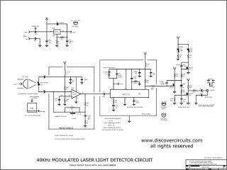
The metal detector circuit includes a fixed frequency oscillator, mixer, detector, detection oscillator, and power amplifier circuit. The fixed frequency oscillator circuit is composed of a ceramic filter (ZC), transistor (V1), resistors (R1 to R4), capacitor (C2), and other...
Hello everyone. This is my first post in quite some time. I obviously do not have an old enough catalog for reference. In the data section, there were references to... The input data indicates a lack of sufficient information regarding...
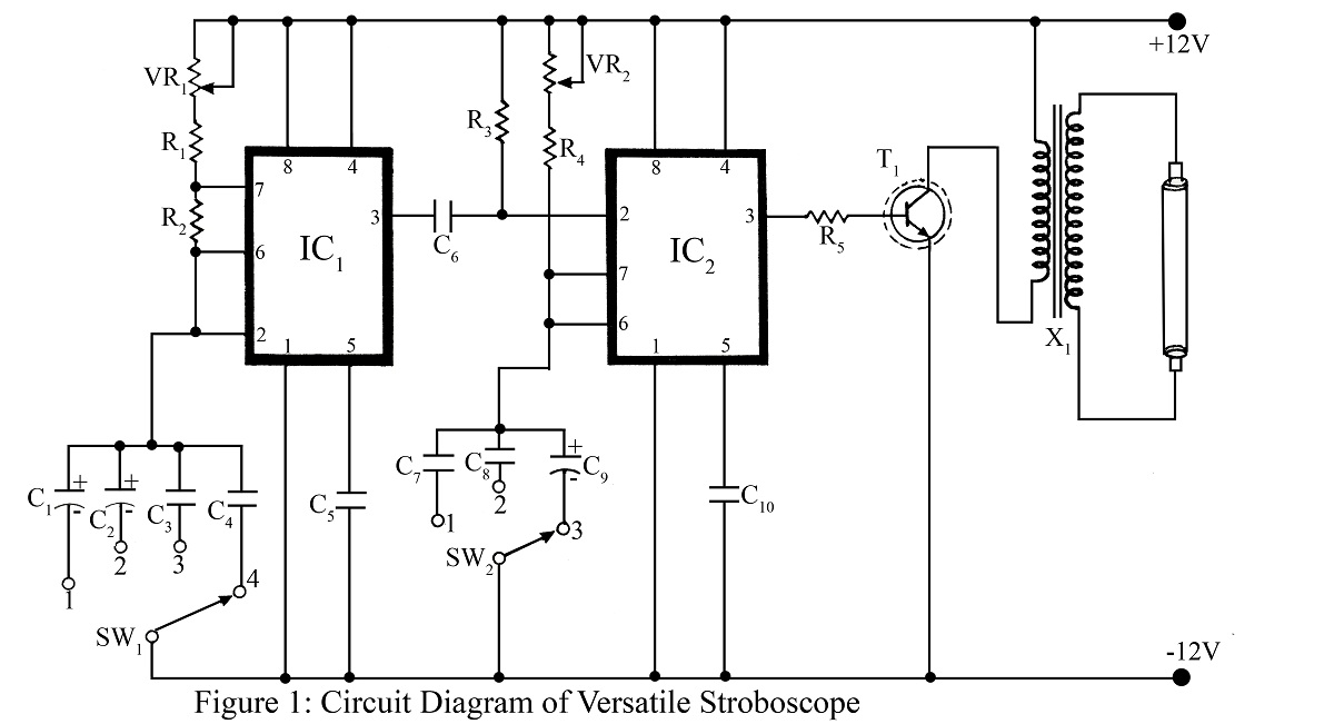
A stroboscope is an instrument used to observe rapidly moving objects with periodic motion as if they are stationary. The strobe light flashes at a frequency that synchronizes with the rotation of a wheel or moving object, creating the...
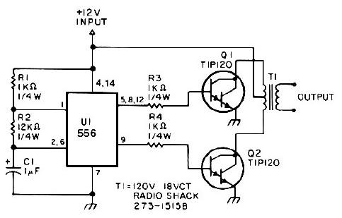
This low-power 25-watt power inverter circuit utilizes only nine electronic components. The inverter converts a DC input voltage ranging from 10V to 16V into a 60Hz, 115V square-wave power output, capable of powering AC electronic devices up to approximately...
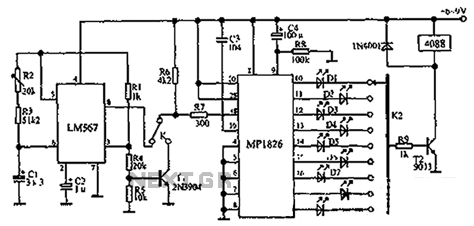
The circuit illustrated in the figure incorporates the MP1826 as a multi-stage divider. The LM567 serves as the frequency demodulation component, functioning as a dual-band oscillator that generates the desired low-frequency pulse from the MP1826. The oscillation center frequency...