
Walkman amplifier
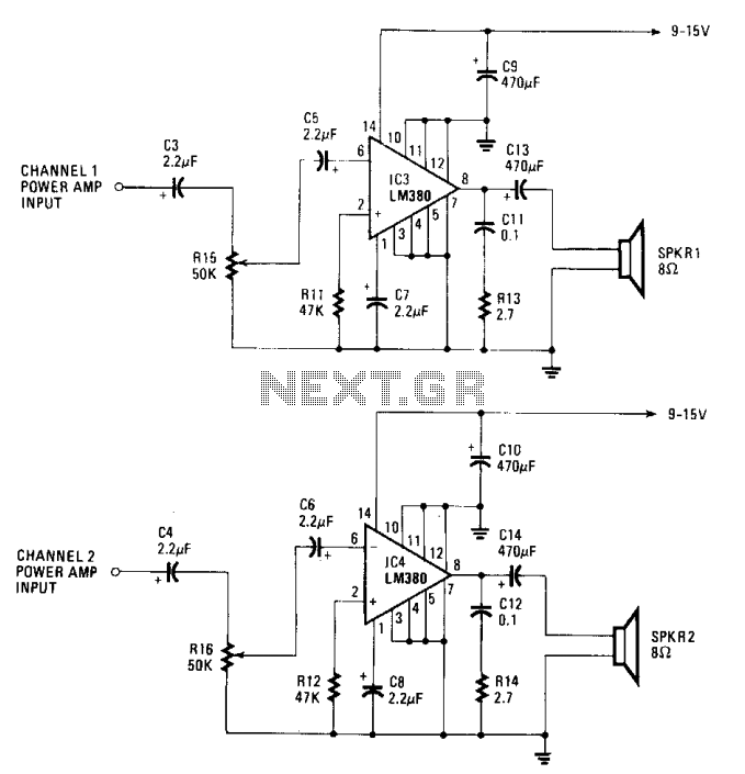
The described circuit utilizes a low-cost integrated circuit (IC) amplifier with a fixed gain of 34 dB, making it suitable for various audio applications. The amplifier's design incorporates a unique input stage that allows for grounding of input signals, which is essential for eliminating noise and ensuring signal integrity. The output configuration is designed to self-center at half of the supply voltage, ensuring that the output signal remains within the linear operating range of the amplifier, thus preventing distortion.
The circuit is capable of delivering around 1.5 watts per channel when powered by a 15-volt supply and connected to an 8-ohm load, making it suitable for driving small speakers. The input stage is versatile, accepting signals from 50 mV to 500 mV rms, which covers a wide range of audio sources. However, for sources such as phonographs or electric guitars that typically output lower signal levels, a preamplifier is necessary to boost the signal before it reaches the main amplifier.
The preamplifier circuit employs two 741 operational amplifiers (op-amps), which are configured to amplify the input signals. The reference voltage for the input stages of these op-amps is established at half the supply voltage, achieved through a voltage divider composed of two 2.2 kΩ resistors (R1 and R2). This configuration allows for balanced operation of the op-amps, enhancing performance and stability.
The gain of each op-amp is set to 21, determined by the values of the input resistors (R9 and R10). This fixed gain ensures that the output from the preamplifier is adequate for the main amplifier stage. Additionally, input capacitors C1 and C2 are included to block any DC offset present in the incoming audio signals, allowing only the AC component to pass through for amplification. This filtering is crucial for maintaining audio quality and preventing unwanted DC levels from affecting the amplifier's operation.
Overall, the described circuit represents a robust solution for audio amplification, integrating effective gain stages and signal conditioning to accommodate a variety of audio sources.The gain of the low-cost IC is internally fixed so that it is not less than 34 dB (50 times). A unique input stage allows input signals to be referenced to ground. The output is automatically self centering to one half the supply voltage. The output is also short-circuit proof with internal thermal limiting. With a maximum supply of 15 volts and an 8 ohm load, the output is around 1.5 watts per channel. The input stage is usable with signals from 50 mV to 500 mV rms. If the amplifier is to be used with a source other than a personal stereo, such as a phonograph or an electric guitar, some type of preamplifier is required. A suitable circuit is shown. In that circuit, two 741 op amps have been configured as input amplifiers. Their input stages referenced to a common point—half the supply voltage. That voltage is derived from a voltage divider made up of Rl and R2, two 2.2 k resistors. The gain of each of the 741's has been fixed at 21 by the input resistors (R9, RIO). Input capacitors; Cl and C2, are used to-filter out any dc component from the input signal than a personal stereo, such as a phonograph or an electric guitar, some type of preamplifier is required. A suitable circuit is shown. In that circuit, two 741 op amps have been configured as input amplifiers. Their input stages referenced to a common point—half the supply voltage. That voltage is derived from a voltage divider made up of Rl and R2, two 2.2 k resistors. The gain of each of the 741's has been fixed at 21 by the input resistors (R9, RIO). Input capacitors; Cl and C2, are used to-filter out any dc component from the input signal. 🔗 External reference
Related Circuits
The ICs LM4651 and LM4652 are types of MOSFET integrated circuits and power amplifiers that include high-efficiency amplifiers, making them suitable for self-powered speakers, subwoofers, and high-quality car audio systems. The LM4651 is a fully integrated conventional pulse width...
This circuit deactivates an amplifier or any connected device when a low-level audio signal at its input is absent for at least 15 minutes. By pressing P1, the device is powered on, supplying power to any appliance connected to...
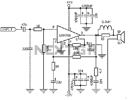
The NS LM4766, launched by a US company, is a two-channel power amplifier integrated circuit. Each channel can output an average power of 40W at an 8-ohm load, with distortion levels lower than 0.1%. It is part of National...
This electret microphone amplifier is constructed using standard electronic components. It is designed to work with an electret microphone capsule, although it can also accommodate a dynamic microphone that has low resistance. The circuit operates with a supply voltage...
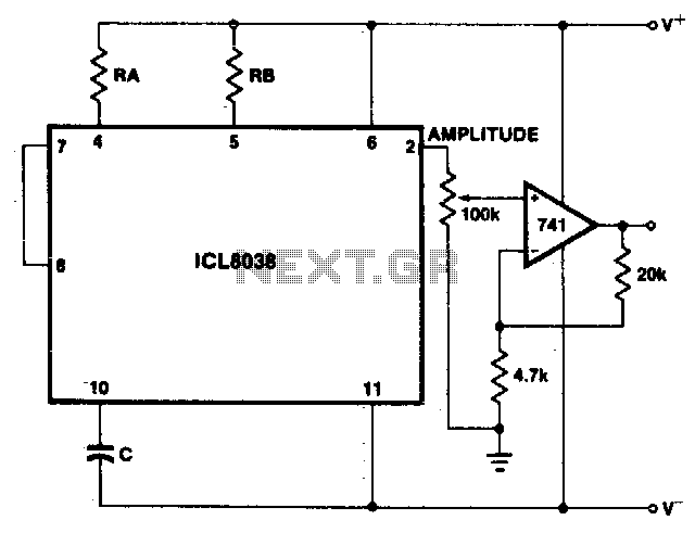
The sine wave output has a relatively high output impedance (1K typical). The circuit provides buffering, gain, and amplitude adjustment. A simple operational amplifier follower could also be used. The described circuit is designed to generate a sine wave output...
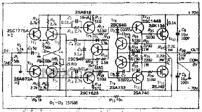
The south circuit consists of four parts, arranged in descending order: an NPN transistor dynamic garbage device (T1), a PNP transistor differential amplifier (T2, T3) forming a double differential circuit, two balanced output amplifiers with opposite phase, and a...
Warning: include(partials/cookie-banner.php): Failed to open stream: Permission denied in /var/www/html/nextgr/view-circuit.php on line 713
Warning: include(): Failed opening 'partials/cookie-banner.php' for inclusion (include_path='.:/usr/share/php') in /var/www/html/nextgr/view-circuit.php on line 713