
Water Level Indicator With Alarm
The circuit operates on the principle of water conductivity to create a reliable water level indicator and alarm system. The CD4066 IC functions as a bilateral switch, allowing current to flow in both directions when activated. The circuit is designed to monitor multiple levels of water, with each LED representing a specific water level. The use of a 180K resistor ensures that the switch remains open when the tank is empty, preventing false indications.
As the water level rises, conductive paths are established through the submerged wires connected to the switches. The first wire closure activates LED1, providing an initial indication of water presence. Subsequent LEDs light up as additional wires are shorted, giving a visual representation of the increasing water level. This arrangement allows for a clear and intuitive understanding of how full the tank is.
The buzzer activation is a critical feature of the circuit, serving as an alert when the tank reaches its maximum capacity. The BC148 transistor acts as a switch, which is turned ON by the water level. When the water fills the tank completely, it provides the necessary voltage to the transistor's base, allowing current to flow from the collector to the emitter, thus energizing the buzzer. The inclusion of an SPST switch allows manual control over the buzzer, enabling it to be silenced after the alarm has been triggered.
For enhanced functionality, the circuit can be expanded to indicate up to eight water levels by incorporating a second CD4066 IC. This scalability makes the design versatile and suitable for various applications, from domestic water tanks to larger industrial storage systems. Proper consideration should be given to the placement of the conductive wires and the overall circuit layout to ensure accurate operation and reliability.This circuit not only indicates the amount of water present in the overhead tank but also gives an alarm when the tank is full. The circuit uses the widely available CD4066, bilateral switch CMOS IC to indicate the water level through LEDs.
When the water is empty the wires in the tank are open circuited and the 180K resistors pulls the switch low hence opening the switch and LEDs are OFF. As the water starts filling up, first the wire in the tank connected to S1 and the + supply are shorted by water. This closes the switch S1 and turns the LED1 ON. As the water continues to fill the tank, the LEDs2, 3 and 4 light up gradually. The no. of levels of indication can be increased to 8 if 2 CD4066 ICs are used in a similar fashion. When the water is full, the base of the transistor BC148 is pulled high by the water and this saturates the transistor, turning the buzzer ON.
The SPST switch has to be opened to turn the buzzer OFF. Remember to turn the switch ON while pumping water otherwise the buzzer will not sound! 🔗 External reference
Related Circuits
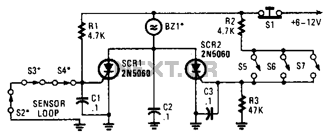
Two SCRs are utilized with two sensor loops. One loop employs series switches, while the other loop employs parallel switches. When a switch is actuated, the SCR is triggered. The alarm is designed to be a non-interrupting type. The circuit...
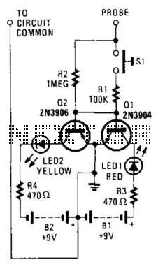
This circuit utilizes two switching transistors and two LEDs to differentiate between low-level AC and DC signals. A lit red LED indicates a positive DC signal, while a lit yellow LED signifies a negative DC signal. If the input...
This is a simple circuit of a beeper using a 555 timer. This circuit can be employed to energize lights, horns, or other signaling devices at any desired interval. The 555 timer is a versatile integrated circuit widely used in...

No setup is required: if correct values are used for resistors R3 to R7, LED D1 will illuminate at 0 dB input (0.775V RMS), LED D2 at +5 dB input (1.378V RMS), and LED D3 at +10 dB (2.451V...
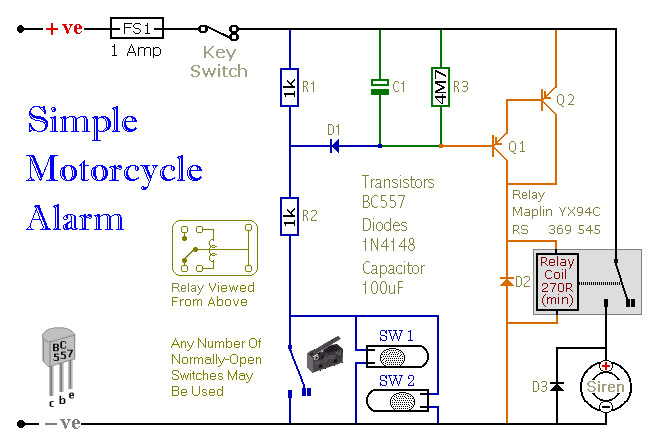
This is a simple easy to build transistor based motorcycle alarm. It is designed to work at 12 volts. But if you change the relay for one with a 6-volt coil, it will protect your Classic Bike. The standby...
Have you ever seen the stairs to one of the upper stories in your house turn into a waterfall? Or maybe you've come home to find your aquarium fish trying to... The provided description suggests a scenario involving unexpected water...