
Series Parallel Loop Alarm Circuit
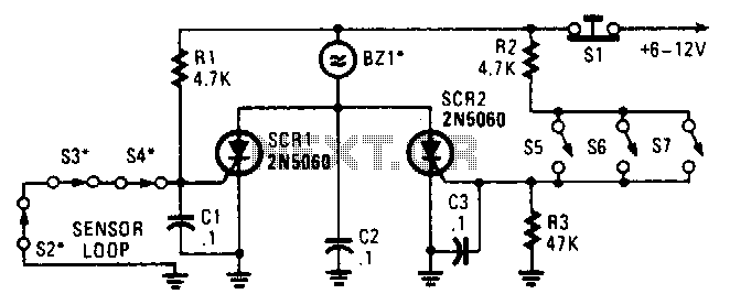
The circuit described involves the integration of two Silicon Controlled Rectifiers (SCRs) within a sensor-based alarm system. Each SCR is connected to a distinct sensor loop, which can be configured differently to accommodate various application requirements.
In the first sensor loop, series switches are employed, meaning that the switches must all be closed to complete the circuit and trigger the SCR. This configuration is beneficial for applications where multiple conditions must be met before an alarm is activated, ensuring a higher level of security or control.
Conversely, the second sensor loop utilizes parallel switches. In this arrangement, the SCR will trigger if any one of the parallel switches is actuated. This setup is advantageous for scenarios where immediate response is required, as it allows for a quicker alarm activation with less dependency on multiple conditions.
The SCRs act as electronic switches that are controlled by the gate voltage applied to them. When a switch in either loop is actuated, it sends a signal to the gate of the corresponding SCR, causing it to conduct and thus activating the alarm system.
The design stipulates that the alarm should be non-interrupting, which implies that once triggered, the alarm will continue to sound or indicate until manually reset or until the triggering condition is removed. This feature is crucial in environments where persistent alerts are needed to ensure that the condition prompting the alarm is addressed without delay.
Overall, this circuit arrangement provides flexibility in sensor configuration while ensuring reliable alarm activation through the use of SCRs, tailored to meet specific operational requirements. Two SCRs are used with two sensor loops. One loop uses series switches, the other loop parallel switches. When a switch actuation occurs, the SCR triggers. The alarm should be a noninterrupting type. 🔗 External reference
Related Circuits
An H-bridge is a type of circuit utilized for controlling the direction (and occasionally the speed) of an electric motor by employing a single polarity voltage. The circuit functions by reversing the current flow to change the motor's rotation...
An average ability amplifier characterized by acceptable overall quality, while being simple in construction. It is frequently used in live loudspeakers. The design incorporates high-quality FET transistors, specifically HEXFET technology, which are voltage-controlled rather than conventional bipolar transistors. The...
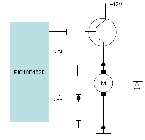
A speed closed-loop control system for a DC motor utilizes back EMF sensing. To implement this, a DC motor is operated in one direction, substituting the LED with the motor and omitting the current limit resistor. It is important...
The series of decibel meters functions to determine the signal strength level delivered to the speakers in an audio system. This decibel meter circuit is commonly referred to as VU meters in high-fidelity audio systems. The series of decibel...
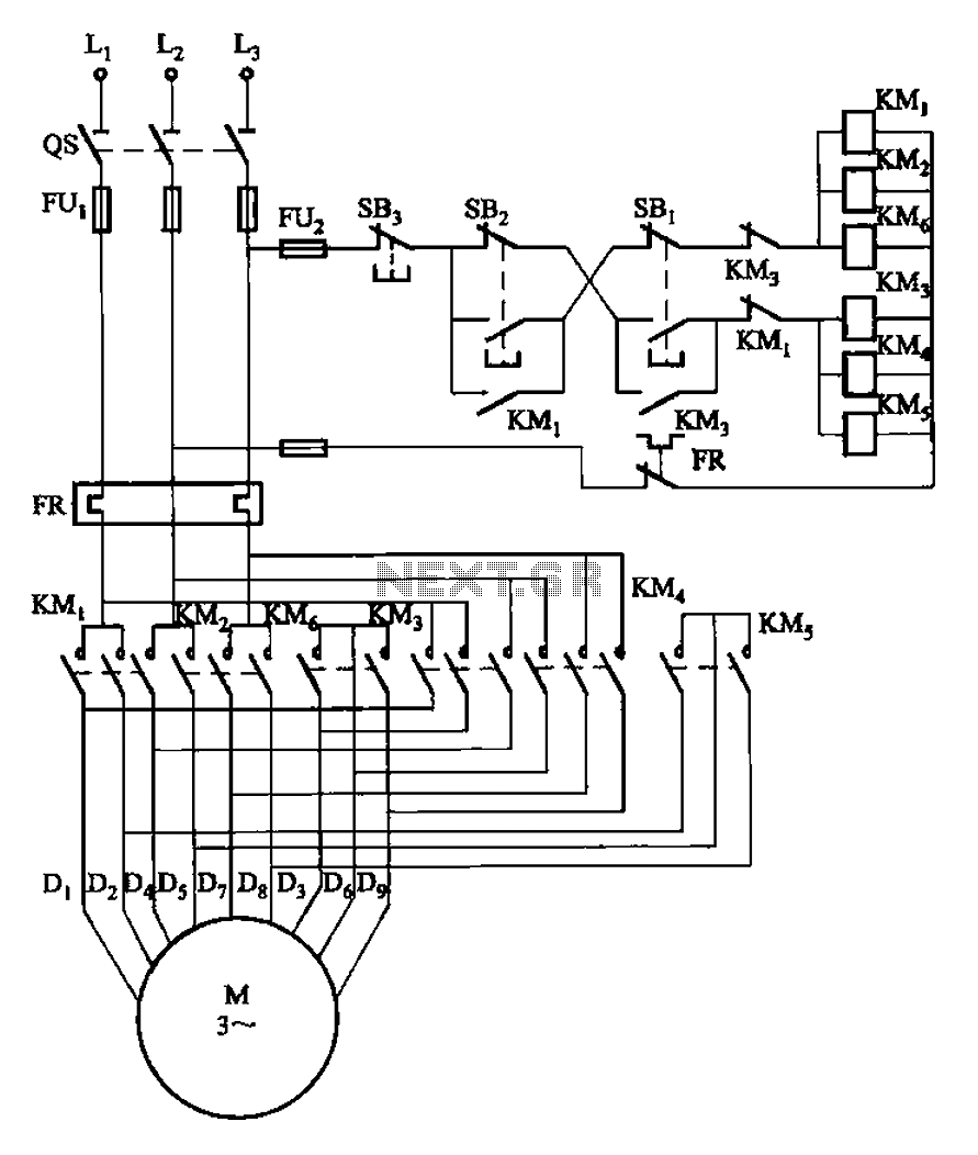
The circuit illustrated in Figure 3-107 features a low-speed operation button (SBi) and a high-speed operation button (SB2). The circuit design depicted in Figure 3-107 integrates two operational modes controlled by distinct buttons: SBi for low-speed operation and SB2 for...
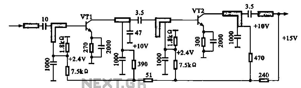
An IF pre-amplifier circuit is presented in a distributed-parameter microstrip configuration. It operates within the frequency range of 950 to 1,470 MHz. The output impedance is approximately 75 ohms. The power supply for the circuit is connected to the...
Warning: include(partials/cookie-banner.php): Failed to open stream: Permission denied in /var/www/html/nextgr/view-circuit.php on line 713
Warning: include(): Failed opening 'partials/cookie-banner.php' for inclusion (include_path='.:/usr/share/php') in /var/www/html/nextgr/view-circuit.php on line 713