
wein bridge oscillator

The Wien-bridge oscillator is composed of a combination of resistors and capacitors arranged in a bridge configuration. The essential components include two resistors (R1 and R2) and two capacitors (C1 and C2), which form the Wien bridge. The output is typically taken from the junction of one of the resistors and one of the capacitors. The circuit employs an operational amplifier (op-amp) as the active element, which provides the necessary gain for oscillation.
To achieve oscillation, the gain of the op-amp must be carefully controlled. A common method for gain control is to use a thermistor or a light-dependent resistor (LDR) in the feedback loop. The resistance of these components varies with temperature or light intensity, respectively, allowing for automatic gain adjustment. This feedback mechanism ensures that the amplitude of the output sine wave remains stable, preventing distortion or clipping.
The phase shift network is critical for maintaining the stability of the oscillation. In the Wien-bridge configuration, the resistors and capacitors are selected such that they introduce a total phase shift of 360 degrees at the desired frequency of oscillation. This is achieved through careful selection of the component values, which can be calculated using the formula for the frequency of oscillation, given by:
\[ f = \frac{1}{2\pi R \sqrt{C1 \cdot C2}} \]
Where \( R \) is the resistance of R1 and R2 (assuming they are equal). The output frequency can be adjusted by varying the resistance or capacitance values.
In summary, the Wien-bridge oscillator is an essential circuit in electronics, particularly for applications requiring stable sine wave generation. Its unique ability to self-regulate amplitude through feedback and phase shifting makes it a versatile tool in signal generation and processing applications.The Wien-bridge oscillator is a unique circuit because it generates an oscillatory output signal without having a sinusoidal input source. Instead, it uses capacitors with initial voltages to create the output. This circuit can be especially useful if connected to a voltage follower to de-couple the load from the source.
ANS; A Wien bridge o scillator produces sine waves. In order for the sine waves to maintain a steady amplitude, a positive feedback system is used with some sort of control to limit gain. In order for the positive feedback system to work, the waves being "fed back" to the amplifier have to be in phase with the waves being generated.
Thus, you need a phase shift network to ensure that the phases of the waves match, which in the case of a positive feedback system means that the generated waves need to go through a 360o phase shift during the feedback process. 🔗 External reference
Related Circuits
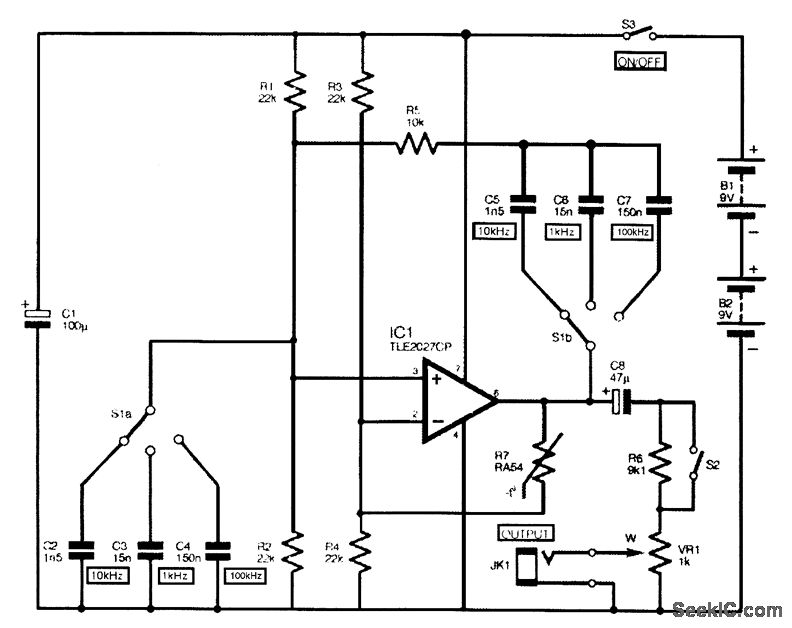
The complete circuit diagram for the audio sine-wave generator is presented. Resistors R1 and R2 provide biasing to the non-inverting (pin 3) input of IC1, and their parallel resistance constitutes one component of the Wien network. They correspond to...
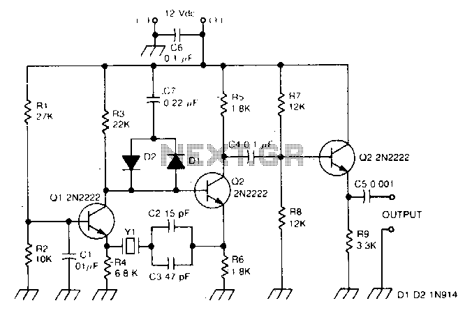
This circuit operates effectively within the frequency range of 50 kHz to 500 kHz. Minor component modifications are required for functioning at higher frequencies. For frequencies exceeding 3000 kHz, it is advisable to choose a transistor that offers moderate...
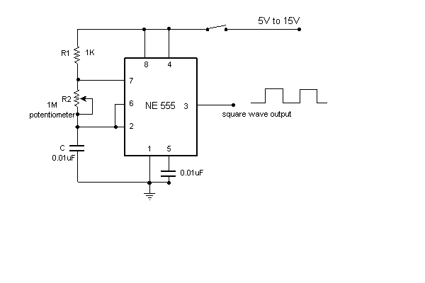
This is a very simple circuit utilizing a 555 timer IC to generate a square wave of frequency that can be adjusted by a potentiometer. With values given, the frequency can be adjusted from a few Hz to several...
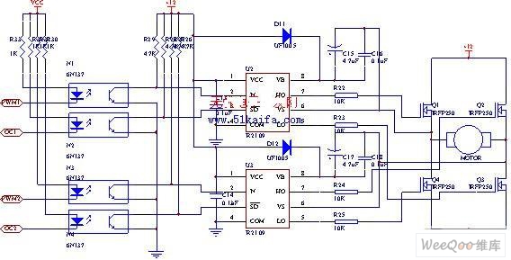
The drive circuit for the electromotor comprises a FET bridge circuit, a FET base drive circuit, a current sensor for the motor drive circuit, and a relay. The FET bridge circuit primarily consists of four high-power MOSFETs, which must...
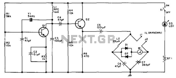
This bridge will measure inductances from approximately 1 to 30 at a test frequency of 5 mHz. A 365-pF AM-type tuning capacitor is utilized as a variable element. The circuit should be assembled within a metal enclosure. Calibration can...
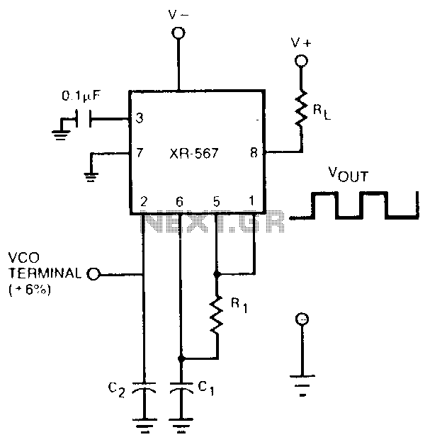
The oscillator output of the XR-567 can be amplified using the output amplifier and high-current logic output available at pin 8. In this manner, the circuit can switch 100-mA load currents without sacrificing oscillator stability. The oscillator frequency can...