Inductance Bridge
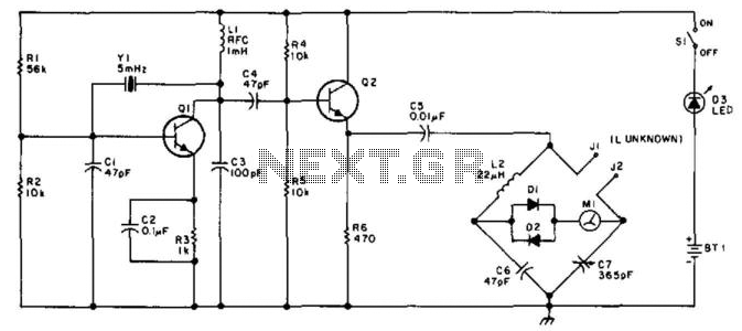
This bridge will measure inductances from approximately 1 to 30 at a test frequency of 5 mHz. A 365-pF AM-type tuning capacitor is utilized as a variable element. The circuit should be assembled within a metal enclosure. Calibration can be performed using known inductors or by plotting a curve of the capacitance of the 365-pF capacitor against rotation and calculating the inductance from this. The measurement range can be adjusted by employing a different frequency crystal and/or varying L2 and C6.
The described inductance measurement bridge operates within a specified frequency range, making it suitable for low-frequency applications. The primary component, a 365-pF AM-type tuning capacitor, serves as a variable capacitor, allowing for fine adjustments in capacitance that are critical for accurate inductance measurements. The bridge configuration typically involves a combination of resistors, capacitors, and inductors arranged to create a balanced circuit, where the unknown inductance can be determined by comparing it against known values.
The metal enclosure is essential for shielding the circuit from electromagnetic interference, which could affect measurement accuracy. Proper grounding and layout practices should be observed to minimize noise and ensure stable operation.
Calibration is a vital step in ensuring measurement accuracy. This can be achieved by using known inductors to establish reference points or by creating a calibration curve that relates the capacitance of the variable capacitor to its rotation angle. This method allows for a more versatile approach to measurement, as it can accommodate variations in component tolerances and environmental factors.
The ability to modify the measurement range by changing the frequency crystal or adjusting components L2 and C6 adds to the flexibility of the bridge. This adaptability is particularly advantageous when measuring inductances across different ranges or in varying application scenarios. The choice of frequency can significantly impact the sensitivity and resolution of the measurements, thus careful selection based on the specific use case is recommended. This bridge will measure inductances from about 1 to 30 at a test frequency of 5 mHz. A 365-pF AM-type tuning capacitor is used as a variable element. The circuit should be constructed in a metal enclosure. Calibration can be done on known inductors or by plotting a curve of the capacitance of the 365-pF capacitor versus rotation and calculating the inductance from this. The range of measurement can be charged by using a different frequency crystal and/or variation of L2 and C6.
🔗 External reference
