
White LED Supply Driver II

The circuit described utilizes a basic LED driver that can effectively power white, blue, or UV LEDs with minimal component costs. The primary focus is on achieving a low-cost design with components not exceeding CZK 10. The circuit can be powered by two standard rechargeable NiCd or NiMH batteries, which provide a stable voltage throughout their discharge cycle, making the design suitable for applications where the supply voltage remains relatively constant.
The LED driver is designed in two configurations: one with a rectifier and one without. The rectifier variant has shown increased efficiency during testing, likely due to reduced parasitic capacitance. The use of a Schottky diode (BAS85) in the rectifier configuration introduces some negative resistance, which can affect performance but is compensated by the overall efficiency gains.
The circuit's output current can be adjusted by modifying the resistor R1 or the capacitor C1. Increasing R1 will reduce the LED current, while increasing C1 will lower the current by affecting the charging time. The recommended resistance range for R1 is between 18 and 22 kilohms when operating at a supply voltage of 1.5 V.
Measuring the efficiency of the LED driver presents challenges due to the pulsed nature of the supply voltage and the potential for measurement distortion when using standard multimeters. To overcome this, an indirect measurement method is employed, utilizing a photodiode (BPW43) placed in proximity to the LED, with a load resistance of 10 kilohms. This setup allows for the measurement of power consumption and output voltage without interfering with the LED's operation.
Overall, this LED driver circuit offers a practical solution for powering LEDs in low-cost applications, balancing efficiency with simplicity while providing flexibility in current adjustment.The article describes a simple and very cheap to drive white, blue or UV LEDs, used for example in small lamps and testers. The cost of components shall not exceed CZK 10. Converters for white LED has been on the pages of journals described quite enough. When I recently needed a similar drive, I wanted to use the drive transistors . This drive was not the desired range of supply voltages (2 normal cells) very convenient. A solution would be to use a specialized integrated circuit, the drive should not be the cheapest. So I tried some of us published the involvement of simple inverters plus a few others. With no I was not too pleased. Some drives have performance more suitable for demonstration purposes only, while others have very little effect. Several authors have vowed to stabilize or reduce the output current. While such a converter from a really nezv?toval voltage LED current, the "stabilization" was due to saturation of the collector current of the transistor or the supersaturation reactor.
For more voltage converters, the efficiency rapidly dwindled. So I suggested a simple involvement in two variants, which in Figure 1 The main connection I replaced one resistor and capacitor component values ??optimized. The drive does not stabilize the current, but with two rechargeable batteries power NiCd or NiMH does not matter because the voltage discharge for most of the time do not change.
The drive comes in two variants - with and without the rectifier. When experimenting with the traditional components of the more attractive option rectifier. The drive was more effective. The final implementation of the SMD, however, showed relatively large negative resistance of a small Schottky diode (BAS85), while the efficiency of converters with a rectifier was larger, probably due to less parasitic capacities. Efficiency drive can be larger in both cases about 10% using improved coil winding with less resistance.
The tests used a cheap miniature axial choke «Pharmaceuticals (in GM for 3 Electronic CZK). LED current can be adjusted by changing resistor R1 (more resistance, less current), or C1-capacity (more capacity, lower current) voltage to 1.5 V R1 to reduce 18 to 22 kilohms. Measuring the effectiveness of similar drives is always a bit of a problem. Supply voltage is pulsed and rippled. Involvement of the meter in series with the LED very distorted results, because the voltage drop across the meter up to several hundred millivolts.
So I measured the effectiveness indirectly. LED I slipped into a short black plastic tubes, LEDs to have placed a photodiode (BPW43) load resistance of 10 kilohms. The drive I measured the voltage of each power consumption and voltage of the photodiode. In the next "round" I set the same LED and a DC current at which the photodiode at the same voltage. The power drive and power LEDs (ie, power converters), I calculated the force. I am aware that even this method can not be exact. LED-powered DC current of 20 mA will shine like the same power LED as the pulse duty cycle 1:1 current 40 mA.
Measurements in Figure 2 and 3 are also loaded with inaccuracies of measuring instruments - had to be simultaneously measured three quantities, and many digital multimeters do not. The word came to the old pointer-type device, which was toward the end of a rather imprecise. 🔗 External reference
Related Circuits
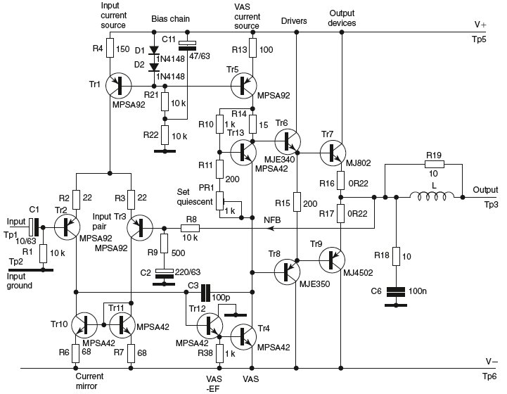
Designs for audio amplifiers with DC coupling to the load are not frequently seen today, despite offering distinct advantages. Audio amplifiers that employ DC coupling to the load provide several benefits that can enhance performance in specific applications. In traditional...
A Variable DC Power Supply is an essential tool for electronics hobbyists. This circuit, while not entirely new, is designed to be simple, reliable, robust, and short-proof. It offers variable voltage up to 24V and variable current limiting up...
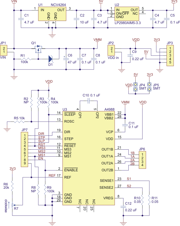
Best 1183 - A4988 Stepper Motor Driver Carrier with Voltage Regulator in Robot Italy. The A4988 stepper motor driver carrier with voltage regulators is a breakout board for Allegro's easy-to-use A4988 microstepping bipolar stepper motor driver. The board has...
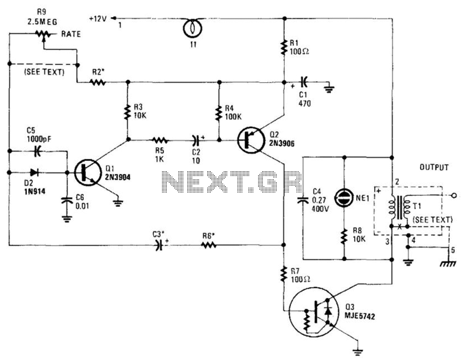
This high-voltage pulse supply generates pulses up to 30 kV. Q1 and Q2 form a multivibrator in conjunction with peripheral components R1 through R6, and C1, C2, C3, C5, C6, and D2. R9 adjusts the pulse repetition rate, while...
The ignition coil driver circuit described is a highly regarded design, reportedly created by Jochen Kronjaeger. It is intended to operate from a 230V source, although a modified version can function effectively at 120V. The circuit requires two ignition...
This document discusses the advantages and disadvantages of various power supply technologies, along with the design considerations necessary for selecting and evaluating a mains transformer. It covers the pros and cons of external supplies, inrush current control, RF emissions...