
Audio amplifier power supply design
The design of power supplies for audio amplifiers necessitates careful consideration of various factors to ensure optimal performance and minimal distortion. Key considerations include the choice of transformer, rectification method, and filtering techniques. Mains transformers serve as the initial stage in power supply design, where their specifications such as voltage ratings, power ratings, and efficiency play a crucial role in overall system performance. The selection of external supplies versus internal supplies can impact both physical layout and electromagnetic interference (EMI) characteristics. Inrush current control mechanisms must also be incorporated to prevent damage to components during the initial power-up phase.
The rectification process, typically achieved using bridge rectifiers, introduces additional considerations such as RF emissions, which can affect the performance of sensitive audio equipment. The design must mitigate these emissions, possibly through the use of filtering techniques or shielding. Moreover, the impact of supply-rail disturbances on audio quality must be addressed through effective bypassing and decoupling strategies. Properly designed rail bypass capacitors with dedicated ground returns can significantly reduce rail decoupling distortion, while careful physical layout can minimize induction distortion.
In terms of filtering, the use of RC filters can effectively smooth out ripple and noise, enhancing the power supply's performance under load conditions. It is essential to ensure that the filtering components are rated for the expected load currents and that the design allows for adequate thermal management. The interaction between power supply performance and amplifier operation is critical, as any ripple or noise introduced during high-current conditions can adversely affect the amplifier's output quality. Therefore, comprehensive testing under various load conditions is necessary to validate the design and ensure that the amplifier maintains low distortion and high fidelity across its operational range.Advantages and disadvantages of different power supply technologies as well as the design considerations involved in choosing and evaluating a mains transformer. The pros and cons of external supplies, inrush current control, RF emissions from bridge rectifiers, and relay supplies.
The literature on power amplifiers frequently discusses the importance of power-supply rejection in audio amplifiers, particularly in reference to its possible effects on distortion [4]! I have (I hope) shown in earlier chapters that regulated power supplies are just not necessary for an exemplary THD performance.
I want to confirm this by examining just how supply-rail disturbances insinuate themselves into an amplifier output, and the ways in which this rail injection can be effectively eliminated. My aim is not just the production of hum-free amplifiers, but also to show that there is nothing inherently mysterious in power-supply effects, no matter what subjectivists may say on the subject.
A proportion of the 100 Hz ripple on the rails will appear at the output, degrading the noise/ hum performance. Most people find this much more disturbing than the equivalent amount of distortion. The rails also carry a signal-related component, due to their finite impedance. In a Class-B amplifier this will be in the form of half-wave pulses, as the output current is drawn from the two supply rails alternately; if this enters the signal path it will degrade the THD seriously.
The second possibility, the intrusion of distortion by supply-rail injection, can be eliminated in practice, at least in the conventional amplifier architecture so far examined. The most common defect seems to be misconnected rail bypass capacitors, which add copious ripple and distortion into the signal if their return lines share the signal ground; this was denoted Distortion 5 (rail decoupling distortion) on my list of distortion mechanisms in Chapter 3.
This must not be confused with distortion caused by inductive coupling of half-wave supply currents into the signal path this effect is wholly unrelated and is completely determined by the care put into physical layout; I labeled this Distortion 6 (induction distortion). Assuming the rail bypass capacitors are connected correctly, with a separate ground return, ripple and distortion can only enter the amplifier directly through the circuitry.
It is my experience that if the amplifier is made ripple-proof under load, then it is proof against distortion components from the rails as well. This bold statement does, however, require a couple of qualifications. Firstly, the output must be ripple-free under load, i. e. with a substantial ripple amplitude on the rails. If a Class-B amplifier is measured for ripple output when quiescent, there will be a very low amplitude on the supply rails and the measurement may be very good, but this gives no assurance that hum will not be added to the signal when the amplifier is operating and drawing significant current from the reservoir capacitors.
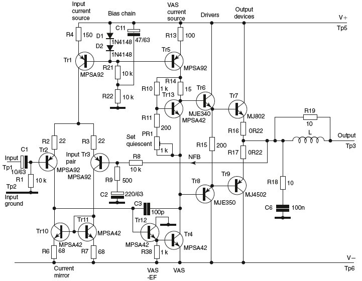
Spectrum analysis could be used to sort the ripple from the signal under drive, but it is simpler to leave the amplifier undriven and artificially provoke ripple on the HT rails by loading them with a sizeable power resistor; in my work I have standardized on drawing 1 A. Thus one rail at a time can be loaded; since the rail rejection mechanisms are quite different for V+ and V-, this is a great advantage.
Drawing 1 A from the V- rail of the typical power amplifier in Figure 9. 7 degraded the measured ripple output from -88 dBu (mostly noise) to -80 dBu. Secondly, I assume that any rail filtering arrangements will work with constant or increasing effectiveness as frequency increases; this is clearly true for resistor-capacitor (RC) filtering, but is by no means certain for electronic decoupling such as the NFB current-source biasing used in the design in Chap 🔗 External reference
Related Circuits
The following circuit diagram depicts a variable power supply controlled by a PIC microcontroller. An LCD display is utilized to show the actual output current and voltage values. This digital power supply incorporates a push-button switch to adjust the...
This circuit is of a 2x 2,500W RMS stereo amplifier, super-light and without switching-mode power supply. The circuit just shows a channel, and the power supply that it assists to the two channels. The audio circuit should be duplicated,...
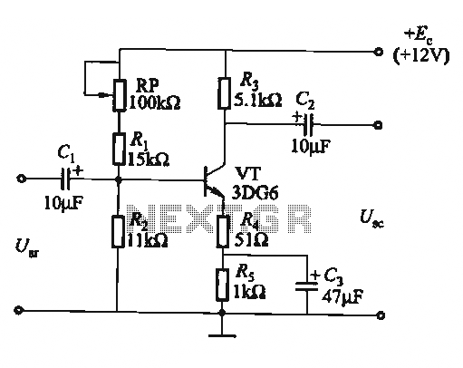
The circuit is a bias circuit for automatic stabilizers that maintains a stable quiescent operating point with good thermal stability. It utilizes a three-pole tube with an NPN type transistor, characterized by a small Iceo. An adjustment potentiometer, RP,...
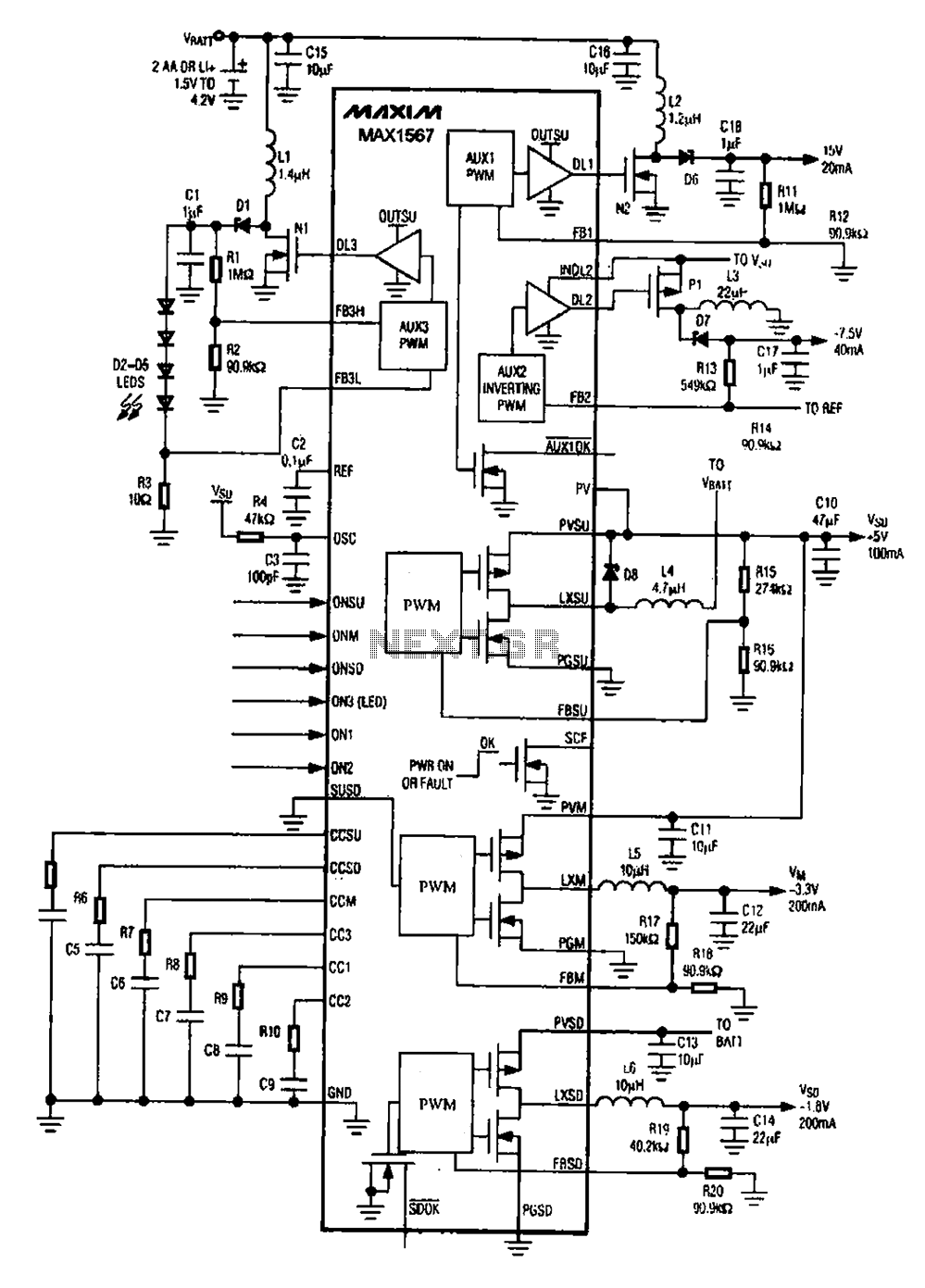
A brush 6-channel camera power supply circuit utilizing the MAX1566/1567. This circuit features a PWM generation system that is divided into six groups, with each group managing a separate channel. The circuit converts the DC voltage from the battery...
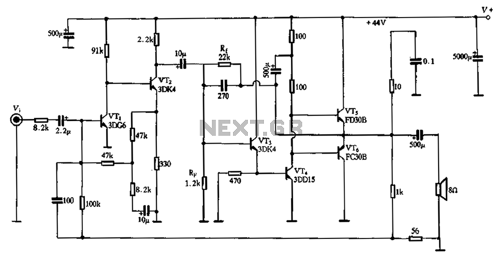
The circuit schematic depicted in Figure 2-3 illustrates a twin direct-coupled input amplifier stage composed of components OV, RLR, and VT2. The emitter of VT2 is connected to the base of VT3, utilizing local feedback to stabilize its DC...
The PCB is at the center of any electronic product. Literally, the enclosure surrounds the board, and figuratively, all the mathematics, the science, the software, these all run on the board. That’s why the PCB is at the center...
Warning: include(partials/cookie-banner.php): Failed to open stream: Permission denied in /var/www/html/nextgr/view-circuit.php on line 713
Warning: include(): Failed opening 'partials/cookie-banner.php' for inclusion (include_path='.:/usr/share/php') in /var/www/html/nextgr/view-circuit.php on line 713