
wideband dtv uhf antenna tv amplifier
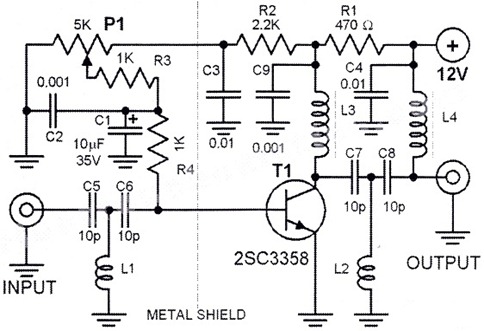
The HD TV UHF wideband amplifier is designed to enhance signal reception for television broadcasts in the UHF frequency range, specifically from 400 MHz to 850 MHz. This amplifier is particularly beneficial in regions where the signal strength is insufficient for reliable TV reception. The gain specification of 10 to 15 dB indicates the amplifier's ability to boost weak signals, thereby improving the quality of the received audio and video.
The construction of the amplifier requires careful attention to the physical layout of the components. SMD components, such as capacitors C1, C2, C6, and C7, are utilized for their compact size and efficiency. These components should be soldered onto the printed circuit board (PCB) with minimal lead length to reduce inductance and capacitance, which can adversely affect performance. Shortening the component pins also helps in minimizing potential interference and maintaining signal integrity.
The choice of a metal enclosure for the amplifier is critical. A metal box not only provides physical protection for the components but also acts as a shield against electromagnetic interference (EMI). This shielding is essential in maintaining the amplifier's performance, particularly in environments with multiple electronic devices that may emit unwanted signals. The amplifier should be positioned as close as possible to the TV antenna to reduce the length of the coaxial cable, which can introduce additional losses.
In summary, the HD TV UHF wideband amplifier is a vital component for enhancing TV signal reception in weak signal areas. Its design must prioritize compactness, shielding, and proximity to the antenna to achieve optimal performance. Proper construction techniques, including the use of SMD components and a metal enclosure, are essential for maximizing the amplifier's effectiveness.This HD TV UHF wideband amplifier(Ultra High Frequency amplifier) has a total gain of 10 to 15 dB in the 400 ? 850 MHz domain frequency so it can be used where the tv signal is weak. For this UHF antenna tv amplifier to work correctly you need to cut the components pins as short as possible.
C1, C2, C6, C7 are SMD type ( surface mounted ). This antenna tv amplifier or uhf wideband amplifier need to be build inside of a metal box and then connected close to the tv antenna 🔗 External reference
Related Circuits
All ATL-3 loop windings are centre tapped and balanced w.r.t. their amplifier/receiver chassis ground, and therefore electric field interference pick up tends to self cancel. Magnetic noise fields, e.g. televisions and the electric meter box, or electromagnetically radiated interferences,...
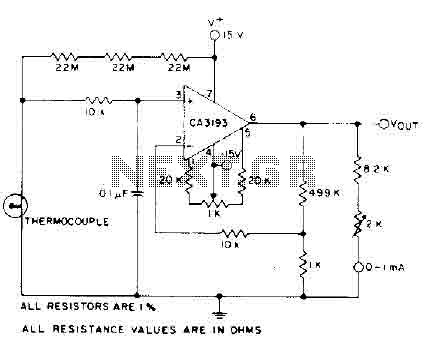
The circuit requires a 15-volt power supply and employs a precision operational amplifier, CA3193 BiMOS, to amplify the generated signal by more than 500 times. Three 22-megohm resistors are utilized to ensure a large-scale output in the event of...
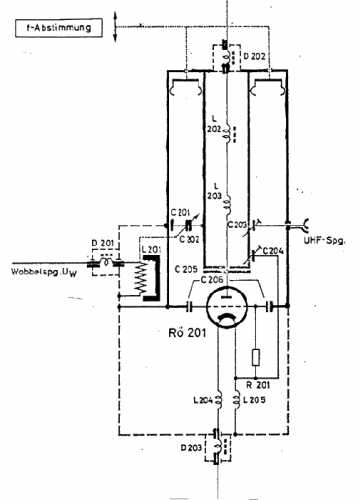
The use of a quarter-wave parallel-wire line as a tuning unit has been discussed in the chapter on Short Lines, where it was pointed out that these circuits have comparatively high Q even at higher frequencies. Their great length...
This is a handy, easy to build general purpose 50 watt amp. The amp has an input for a radio, TV, stereo or other line level device. It also has a phono input for a record player, guitar, microphone...
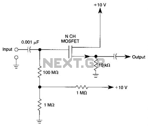
Biasing methods for an N-channel MOSFET to form a unity-gain noninverting amplifier or source-follower. The N-channel MOSFET can be utilized in various configurations, with one common application being the unity-gain noninverting amplifier, also known as a source-follower. In this configuration,...
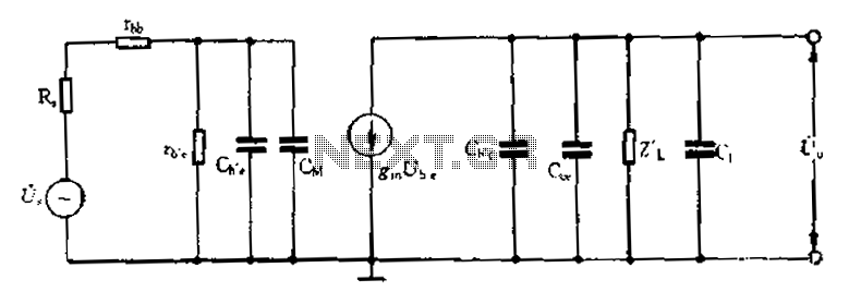
Common emitter amplifier circuit with resistance and capacitance coupling. The common emitter amplifier circuit is a fundamental configuration in analog electronics, widely utilized for its ability to amplify voltage signals. This circuit employs a bipolar junction transistor (BJT) as the...
Warning: include(partials/cookie-banner.php): Failed to open stream: Permission denied in /var/www/html/nextgr/view-circuit.php on line 713
Warning: include(): Failed opening 'partials/cookie-banner.php' for inclusion (include_path='.:/usr/share/php') in /var/www/html/nextgr/view-circuit.php on line 713