
VACUUM TUBES in UHF circuits
The design of a quarter-wave parallel-wire line oscillator circuit is characterized by its ability to produce stable oscillations at ultra-high frequencies (UHF). The circuit employs a quarter-wave transmission line, which acts as a tuning element, providing high quality factor (Q) characteristics essential for efficient operation at these frequencies. The quarter-wave line's physical length is critical; it is designed to be approximately one-quarter of the wavelength of the signal being generated, allowing for optimal impedance matching and energy transfer.
In the configuration, large copper or brass tubes function as the transmission line, and the connections to the vacuum tube are made using short lead wires to minimize inductive losses. The shorting bar, which can be adjusted along the transmission line, serves to fine-tune the frequency output. The placement of the plate and grid taps is strategically designed to maximize the voltage at the open end of the line, thus enhancing the electrostatic energy available for oscillation.
The circuit's stability is further enhanced by ensuring that the taps are positioned optimally along the line. If feedback from the tube is insufficient, the circuit risks entering a state of overload, where oscillations cease. Therefore, careful adjustments are necessary to maintain oscillation, often requiring a balance between the load and the power supply to the vacuum tube.
Additionally, the integration of small capacitors at the open end of the line may be employed to modify the electrical characteristics of the circuit. However, this introduces losses that can adversely affect the Q factor, necessitating adjustments to the physical length of the line to preserve its quarter-wave electrical length.
In applications such as cyclotrons, the tuning circuit can achieve significant voltage levels, with the potential for several hundred thousand volts between capacitor plates. The design also allows for the tuning of multiple circuits, including the filament circuit, to ensure optimal performance across the board. The symmetry of the circuit structure, combined with the use of quarter-wave lines, provides a robust solution for generating stable oscillations at ultra-high frequencies.The use of a quarter-wave parallel-wire line as a tuning unit has been discussed in the chapter on Short-Lines, where it was pointed out that these " circuits " have comparatively high Q even at the higher frequencies. Their great length (l/4) prevents their widespread use at lower frequencies. But when the wave-length is only 1 meter or thereabou ts, the line has reasonable physical dimensions. And it is just in these regions that the requirement of high Q becomes difficult to attain with ordinary circuits. Our purpose now is to learn how to connect a quarter-wave line to a vacuum tube to form an efficient oscillator for the production of ultra-high frequencies.
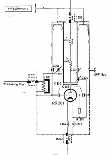
The student should now turn back to Fig. 14 E and study the parallel-fed ultraudion oscillator circuit for a few minutes. Series feed is also possible, as in (a) of Fig. 37 F. The lumped L and C of this circuit is replaced by the quarter-wave line of (b) for u. h. f. Compare (a) and (b) part by part. In general, the LC circuits used in the various types of oscillators of Chapter 14 can be replaced by quarter-wave lines. In the u. h. f. oscillator of Fig. 37 F, large copper or brass tubes may be used for the line. The lead wires to the tube are made as short as possible. The shorting bar can be shifted along the line (within limits) to change the frequency. The plate and grid leads are tapped onto the line as close to the shorted end as possible in order that, for a given voltage from the tube, the open-end voltage may be as high as possible.
The effect is shown in Fig. 37 G. High voltage at the open end means strong electrostatic fields, and this means large electrostatic energy. This is similar to the action of a large flywheel in stabilizing the rotation of a machine. It results in frequency stability in the electrical case. On the other hand, if the tap is too close to the shorted end, the energy from the tube may not be sufficient.
Thus, if a loop of wire is placed near the line to pick up energy for delivery to an antenna, the power output may be so great that the feedback voltages of the tube cannot keep the large storage " tank " filled. Then oscillations cease; the circuit is overloaded. In practice, the taps are shifted toward the shorting bar, with full load on, until oscillations cease.
The tap is moved back a little, or the power supply on the tube is increased until oscillations again take place. It might be added that the impedance of the line is the same when looking in either direction from the taps.
A small capacitance may be connected across the open end of the line in Fig. 37 F. It is then necessary to shorten the physical length of the line in order that its electrical length shall remain one quarter-wave. The losses in the condenser lower the Q of this tuning circuit appreciably. In one application, the capacitance at the open end consists of the " dees " of a cyclotron. R. F. potentials of the order of several hundred thousand volts have been built up between the condenser plates (between the dees) by this method.
It will be noticed in Fig. 37 F, that the filament leads of the u. h. f. circuit contain coils and condensers. The effective or electrical length of this circuit is one-half wave-length. Then the FF terminals will be at the same potential as that at the shorted end of the line. In practice, this condition is found by changing the coils until maximum power output and stability are realized. In general, at the ultra-high frequencies, it is necessary to tune not only the plate and grid circuits but also the filament circuit.
Usually, only two of the three circuits are tuned with high-Q resonant lines. Figure 37 H shows a push-pull circuit in which the grid and plate circuits are tuned with quarter-wave lines, while Fig. 37 I shows a similar circuit with the filament and plate circuits tuned in this manner. These circuits have the advantage of symmetrical structure and increased 🔗 External reference
Related Circuits
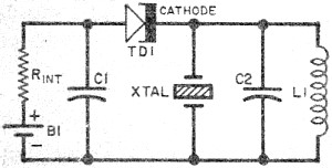
Leo Esaki invented the tunnel diode in 1957 while working at Sony (then known as Tokyo Tsushin Kogyo). Tunnel diodes feature a very narrow, heavily doped p-n junction approximately 10 nm wide, which exhibits a broken bandgap. This configuration...

The ATA5743 is a multi-chip PLL receiver device housed in an SSO20 package. It has been specifically designed to meet the requirements of low-cost RF data transmission systems, supporting data rates ranging from 1 kBaud to 10 kBaud using...
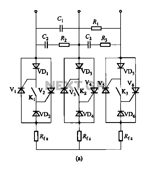
Figure 16-48 (a) illustrates the introduction of a six thyristor three-phase AC switching circuit, while Figure 16-48 (b) depicts the implementation of three triac circuits. These configurations are suitable for motors and other inductive loads. The six thyristor three-phase AC...
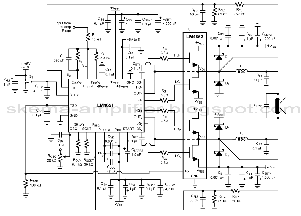
The LA4440 is a two-channel audio power amplifier integrated circuit (IC) designed for stereo and bridge amplifier applications. In dual mode, it provides an output of 6 watts per channel, while in bridge mode, it can deliver up to...
At the beginning of the design process, the designer must determine which circuit structure is appropriate for a specific purpose. During this phase, numerical and symbolic analysis are of limited utility. There are no numerical values available for conventional...

A voltage comparator is a device that compares the voltages at its two inputs and generates an output based on the comparison. It produces a high output when the positive input exceeds the negative input and a low output...