
Wideband high-frequency amplifier
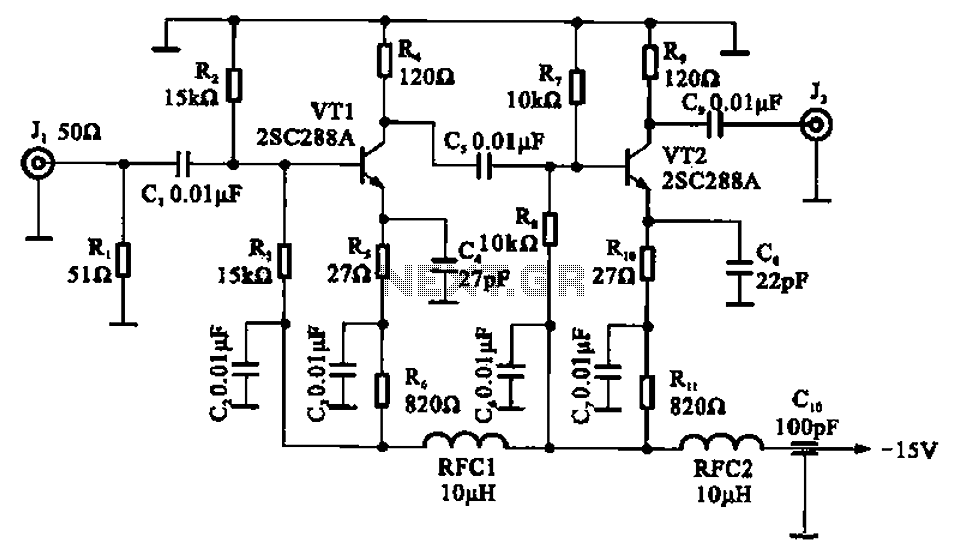
The wideband high-frequency amplifier circuit is designed to operate effectively across a broad frequency range, making it suitable for applications in communications and signal processing. The common emitter configuration is particularly advantageous in this design due to its inherent ability to provide significant voltage gain while maintaining a relatively simple topology.
The circuit includes two transistors, VT1 and VT2, which are configured to work in tandem. The input signal is introduced through a coupling capacitor (C1), which serves to block any DC component while allowing the AC signal to pass. This is crucial for ensuring that the transistors operate within their linear region, thereby avoiding distortion of the amplified signal.
Capacitor C5 plays a vital role in coupling the output of the first transistor (VT1) to the base of the second transistor (VT2). This coupling is essential for cascading the amplification stages and achieving the desired output gain. The choice of capacitors in the circuit, particularly for frequency compensation, is critical. These capacitors help stabilize the amplifier's performance and prevent unwanted oscillations, which can occur at high frequencies.
The output is taken from the collector of the second transistor (VT2), where the amplified signal can be further processed or transmitted. The design allows for tuning the bandwidth by adjusting the values of the capacitors involved, ensuring that the amplifier can maintain a consistent gain across the desired frequency range. The use of high-frequency compensation capacitors is also important in maintaining the integrity of the signal and minimizing phase shifts that could lead to instability.
Overall, this wideband high-frequency amplifier circuit exemplifies the principles of RF amplification, combining careful selection of components and configuration to achieve optimal performance in high-frequency applications.A wideband high-frequency amplifier is shown, the circuit resistance and capacitance coupling of common emitter amplifier can be used to amplify high frequency signals. When th e high-frequency signal Jl end to (input impedance 50 n), applied to the amplifier via a coupling capacitor cl VTI base and amplified by the c5 coupled together to VT2 base, the amplified signal from the collector output. Adjust the band No. capacitor band frequency characteristic can reach l dB, with number of high-frequency capacitor compensation capacitor.
Related Circuits
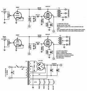
Stereo tube amplifier circuit built with 5 power tubes: 6SQ7-GT, 6V6-GT, and 5Y3-GT. This circuit generates up to 4 watts of audio output per channel. The stereo tube amplifier circuit utilizes a combination of five power tubes, specifically the 6SQ7-GT,...
The project is a variation of the popular POV toy, commonly seen as a beginner electronics project. This year, the decision was made to create a synthesizer kit, incorporating an SPI DAC, audio amplifier, microcontroller, and buttons. Additionally, there...
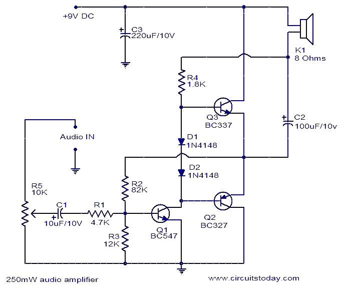
This is a simple three-transistor audio amplifier circuit capable of delivering 250 mW to an 8-ohm speaker. Complementary transistors BC337 and BC227 (Q3 and Q2) are utilized as the output pair, while transistor Q1 (BC547) functions as the preamplifier....
This circuit utilizes a MOSFET amplifier as the primary component for boosting audio signals. It is designed to drive a speaker with an impedance of 8 Ohms and a power output exceeding 200W. Additionally, a suitable power supply circuit...
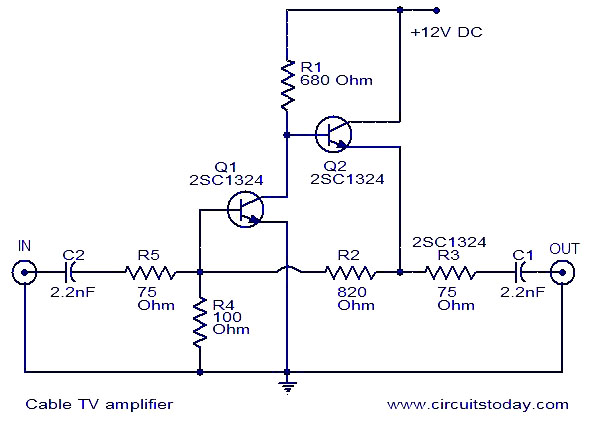
This is a simple cable TV amplifier using two transistors. The amplifier circuit is designed for cable TV systems utilizing 75 Ohm coaxial cables and is effective up to 150 MHz. Transistor T1 is responsible for amplification, providing up...
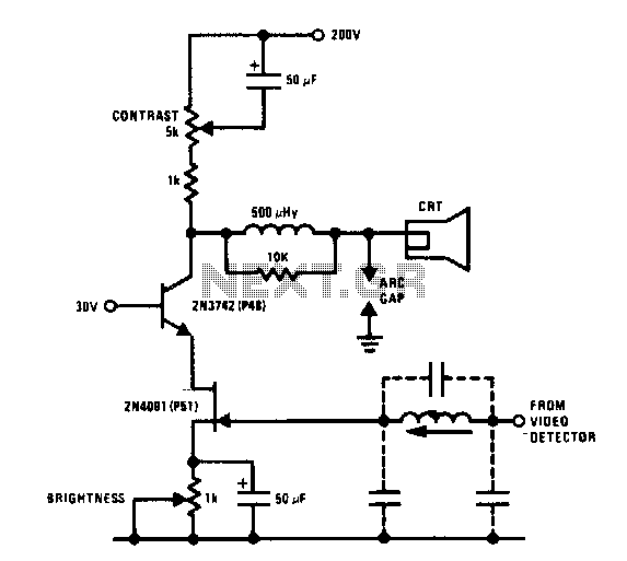
The JFET-bipolar cascode circuit will provide full video output for the CRT cathode drive. Gain is about 90. The cascode configuration eliminates Miller capacitance problems with the 2N4091 JFET, thus allowing direct drive from the video detector. An m-derived...