
Wien Bridge Oscillator
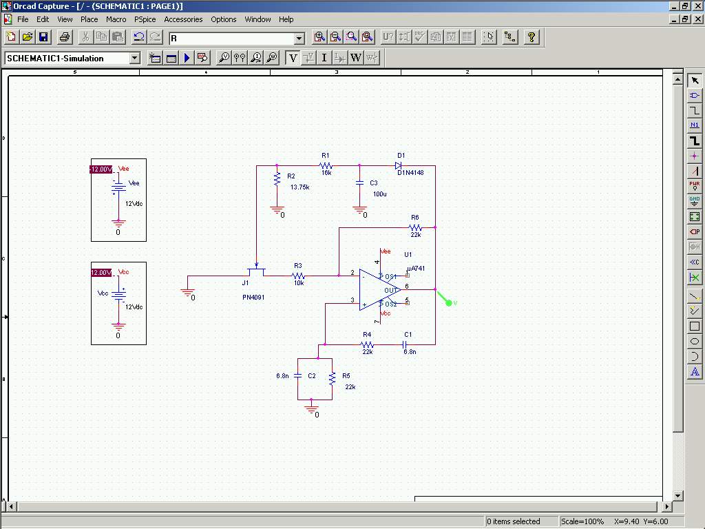
The Wien Bridge oscillator is a popular circuit used for generating sine waves. It comprises an operational amplifier configured to provide positive feedback through a bridge circuit formed by resistors and capacitors. The frequency of oscillation is determined by the values of the resistors and capacitors in the feedback loop. In this case, R4 and R5 are the resistors that set the gain, while C1 and C2 are the capacitors that determine the timing characteristics of the oscillator.
The feedback mechanism is crucial for maintaining stable oscillations. The feedback coefficient of 1/3 indicates that the feedback loop is set to provide a fraction of the output signal back to the input, ensuring that the conditions for sustained oscillation are met. The operational amplifier must have a gain greater than three to satisfy the Barkhausen criterion, which states that the product of the gains around the loop must equal one at the frequency of oscillation.
The inclusion of the FET serves a dual purpose: it stabilizes the gain of the oscillator and prevents distortion in the output waveform, which can occur if the gain is too high. The automatic gain control feature allows the circuit to adapt to variations in output amplitude by adjusting the resistance of the FET based on the output voltage level. This dynamic adjustment of gain helps maintain a clean sine wave output, which is essential for applications requiring precise signal generation.
In summary, the Wien Bridge oscillator designed in this experiment effectively utilizes an operational amplifier, passive components, and an FET to produce a stable 1 kHz sine wave output while ensuring that the signal remains undistorted through automatic gain control.In this experiment, an oscillator is constructed using an operational amplifier and some other passive elements. This configuration for the oscillator is called Wien Bridge. The frequency of the oscillator is determined by R4, R5, C1, and C2 elements. In this circuit, they are chosen so that the frequency is 1 khz. The feedback coefficient ( ²) is 1/3 in this circuit, so gain is chosen 3 or higher to fullfill the Barkhausen oscillation criterion. The negative feedback applied using FET+R3 and R6 determines the gain and because of very existence of the FET, the output won`t be clipped.
The FET works as an AGC: when the output voltage decreases, the magnitude of the negative voltage on the gate of the FET increases, causing its resistance Rds to increase and therefore decreasing the gain of the oscillator ( 1+R6/(R3+Rds) ). This decrease in the gain causes the output not to clip. 🔗 External reference
Related Circuits
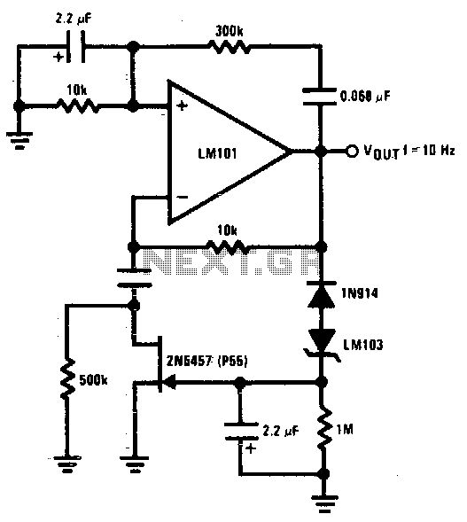
The 2N5457 JFET is utilized as a voltage variable resistor within the amplifier feedback loop, resulting in a low distortion, constant amplitude sine wave and optimizing the amplifier loop gain. The LM103 zener diode serves as the voltage reference...
During experiments with various receivers and amplifiers powered by "free energy," it was discovered that connecting the audio amplifier to the receiver using only two wires for audio signals and supply voltage is more convenient. This setup allows the...
For successful circuit-building exercises, follow these steps: Measure and record all component values before constructing the circuit, selecting resistor values that are sufficiently high to minimize the risk of damaging any active components. In case of significant errors (greater...
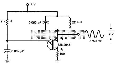
A tuned circuit can be incorporated into the current-pulse path of a UJT oscillator to generate a 3750-Hz sinusoidal signal at output B2, using the specified component values. The UJT (Unijunction Transistor) oscillator is a type of relaxation oscillator that...
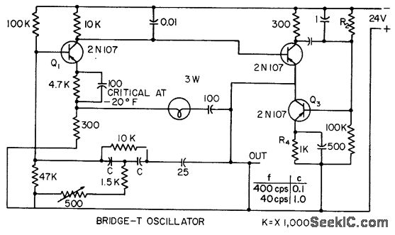
This circuit incorporates heavy degenerative feedback, utilizing a small lamp as a nonlinear compensating resistance. It provides a constant output frequency and voltage for supply voltages ranging from 12 to 32 V, and operates effectively at temperatures as low...
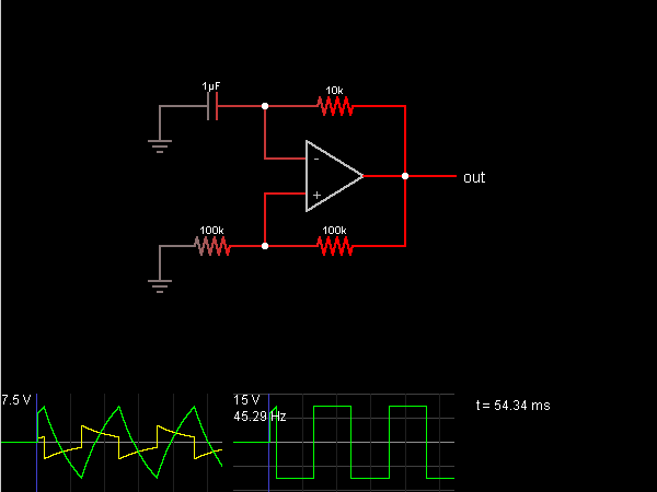
This circuit is an oscillator that generates a square wave. The operational amplifier (op-amp) begins with its two inputs in an undefined state, starting with the non-inverting input slightly higher than the inverting input. The op-amp significantly amplifies this...