
WIND DIRECTION SENSOR

The described circuit operates based on the principles of wind direction measurement. The wind vane, which is designed to pivot according to wind direction, is equipped with a magnet that activates the reed switches. The placement of the eight reed switches in a circular arrangement allows for precise detection of the wind direction by determining which switch is activated by the magnet as the vane rotates.
Each reed switch is a magnetic sensor that closes its contacts in the presence of a magnetic field. As the wind vane turns, the magnet on the vane arm will sequentially activate the reed switches, providing a digital signal corresponding to the specific direction of the wind. This configuration can be particularly useful in applications such as meteorological stations, automated weather monitoring systems, or any project requiring wind direction data.
The electrical connections should ensure that each reed switch is appropriately wired to a microcontroller or an indicator circuit, allowing for easy interpretation of the wind direction data. The output can be processed to display the wind direction in degrees or as a directional indicator, enhancing the functionality of the circuit. Proper calibration of the system may be necessary to ensure accuracy, taking into account the physical layout and spacing of the reed switches relative to the wind vane's movement.To use the circuit you will need a wind vane like the one shown. It should have a weighted front end and an air paddle in the rear. Attach a small, strong magnet to the front part of the wind-vane arm. Then, position eight reed magnetic switches in a circle around a piece of plastic pipe and electrically connect them (as shown). Note that the reed switches a.. 🔗 External reference
Related Circuits

The following circuit illustrates a PIR Sensor Timer Circuit Diagram. Features include a simple design, enhanced accuracy, and efficiency. Components involved are a diode, among others. The PIR (Passive Infrared) Sensor Timer Circuit is designed to detect motion through infrared...
An effective temperature sensor circuit is designed to receive power from a 4-to-20 mA loop without impacting the loop current. The temperature sensor integrated circuit (IC) used is the AD590F, which operates with a supply voltage ranging from 4...

This is a rather sensitive circuit which will detect minute variations of a magnetic field, particularly the Earth magnetic field. The principle is based on an audio beat tone generated by two identical oscillators. These must be built in...

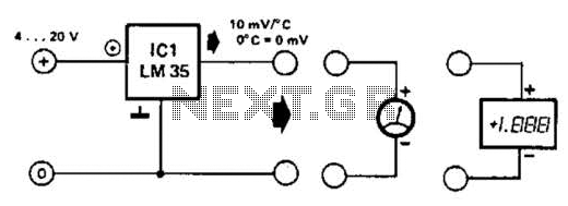
The LM35 temperature sensor outputs 10 mV/C for each degree Celsius above 0°C. At 20°C, the output voltage is calculated as 20 × 10 = 200 mV. The circuit consumes minimal power. Additionally, the load resistance should not be...

This circuit diagram is based on the PIR motion sensor module BS1600 (or BS1700) designed for security lighting in power-saving mode. If the component is unavailable in local stores, it can be purchased online. A key advantage of this...

The CCD camera sensor is a very useful device that is compact in size while providing excellent quality. It can be easily installed with a television through the video input terminals, allowing for the transmission of modulated video signals...