
How to install CCD camera sensor with VHF sender
The CCD camera sensor project is an innovative solution for various surveillance and monitoring applications. Its compact design enables easy integration into existing systems, such as televisions, enhancing their functionality. The ability to operate in low-light conditions with infrared capability is particularly advantageous for nighttime monitoring. The circuit design is straightforward, allowing for DIY assembly, making it accessible to hobbyists and professionals alike.
The power supply circuit is critical to the overall functionality of the CCD camera. The transformer steps down the voltage from 220V AC to 12V AC, which is then rectified by the bridge rectifier formed by the diodes. This conversion is essential for powering the CCD sensor and ensuring optimal performance. The smoothing capacitor plays a vital role in providing a stable DC voltage, necessary for the reliable operation of the camera.
The addition of a wireless video transmitter expands the versatility of the system, allowing for use with televisions that do not have a direct video input. This feature broadens the potential applications of the CCD camera, making it suitable for both residential and commercial security setups. The modulation of the video signal with the radio wave enables seamless transmission, while the option to adjust the receiving frequency ensures compatibility with various television models.
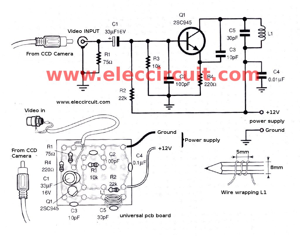
In summary, this CCD camera project combines practical design with advanced functionality, making it an effective tool for surveillance and monitoring in diverse environments. Its ease of installation and adaptability to different applications make it a valuable addition to any security system.The CCD camera sensor is device that have very useful. This project has small size. But quality is a lot good. We can install with Television easily through the video in terminals. and connects to the video signal modulated to To send a broadcast RF signal is explicit is better. This project can be adapted to many applications such as installed in the bedroom children. To noticed the baby through the TV monitor. or When guest press a doorbell the front yard, we will know is who. or Application of an intercom to contact the visible image once. Installed in shops, factories and other places to secure it better. This small CCD camera video are model of ready-made digital camera has the connecting to use of 3 wire. Able to work in the dark or under illumination 0. 1 lux. Using an infrared beam. As described above the CCD model can be easily apply just correctly connects the power supply. We will be obtained the video signal level 10 volts peak to peak at impedance of the signal wire 75 ohms then connect to TV that has Video in immediately.
But we must build the power supply circuit add the 1 set. By the characteristics of the circuit as follow in Figure 2. The working of power supply section will have the transformer T1 converts from AC220V to AC12V only, then into the D1-D4 diodes that is connected as the bridge rectifier into DCV out to C1-capacitor, which acts as a smoothing filter current is DCV again We need to create a section of the power supply circuit. As the PCB layout and the positioning equipment in Figure 3 Which can build by yourself easily. or If you do not want to use the PCB can be soldered directly to the equipment in Figure 4. We able to optimize this project with the Simple video transmitter circuit In the wireless to can be used with televisions that without the Video in port.
as show in Figure 5 to bring the video signal from the CCD camera immediately. In circuit has transistor Q1 number 2SC945 or others such as 2SC458, 2SC1815 etc. They are used to modulation the radio wave mix together with the video signal then send to broadcast. By range that can receiver will be in range VL (VHF) so adjust in 2, 3 and 4 channel. How to tune the TV easily. Starting assemble the circuit to be available. then placed near the transmitter and receiver. Then adjust the tuner to channel 3. After that move L1 or freqency of receiver, we would have been waves from the transmitter. 🔗 External reference
Related Circuits

The robot requires a method for detecting obstacles (or other robots) without making physical contact. This capability allows the robot to determine whether to avoid or confront and investigate the obstacle based on its programming. This document outlines the...
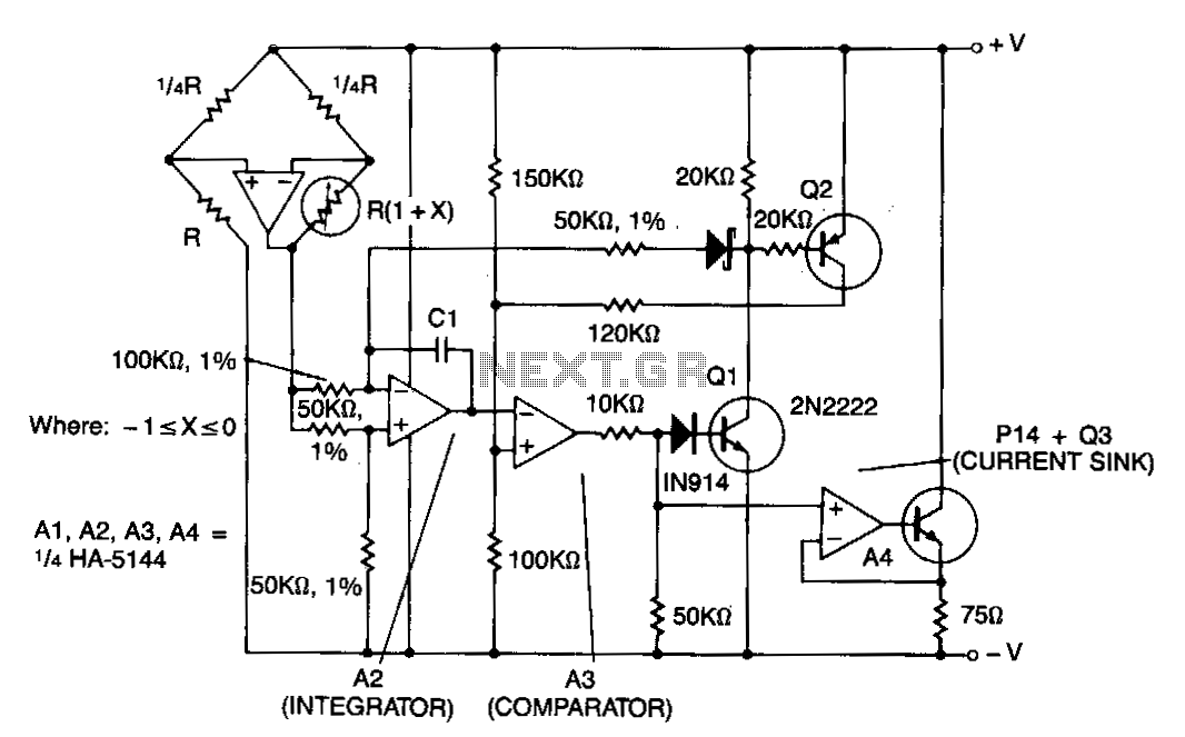
This circuit features amplifier A1 as a sensor amplifier configured in a bridge arrangement. Amplifiers A2 and A3 are set up as a voltage-to-frequency converter, while A4 functions as the transmitter. The entire sensor/transmitter operates directly from a 4...
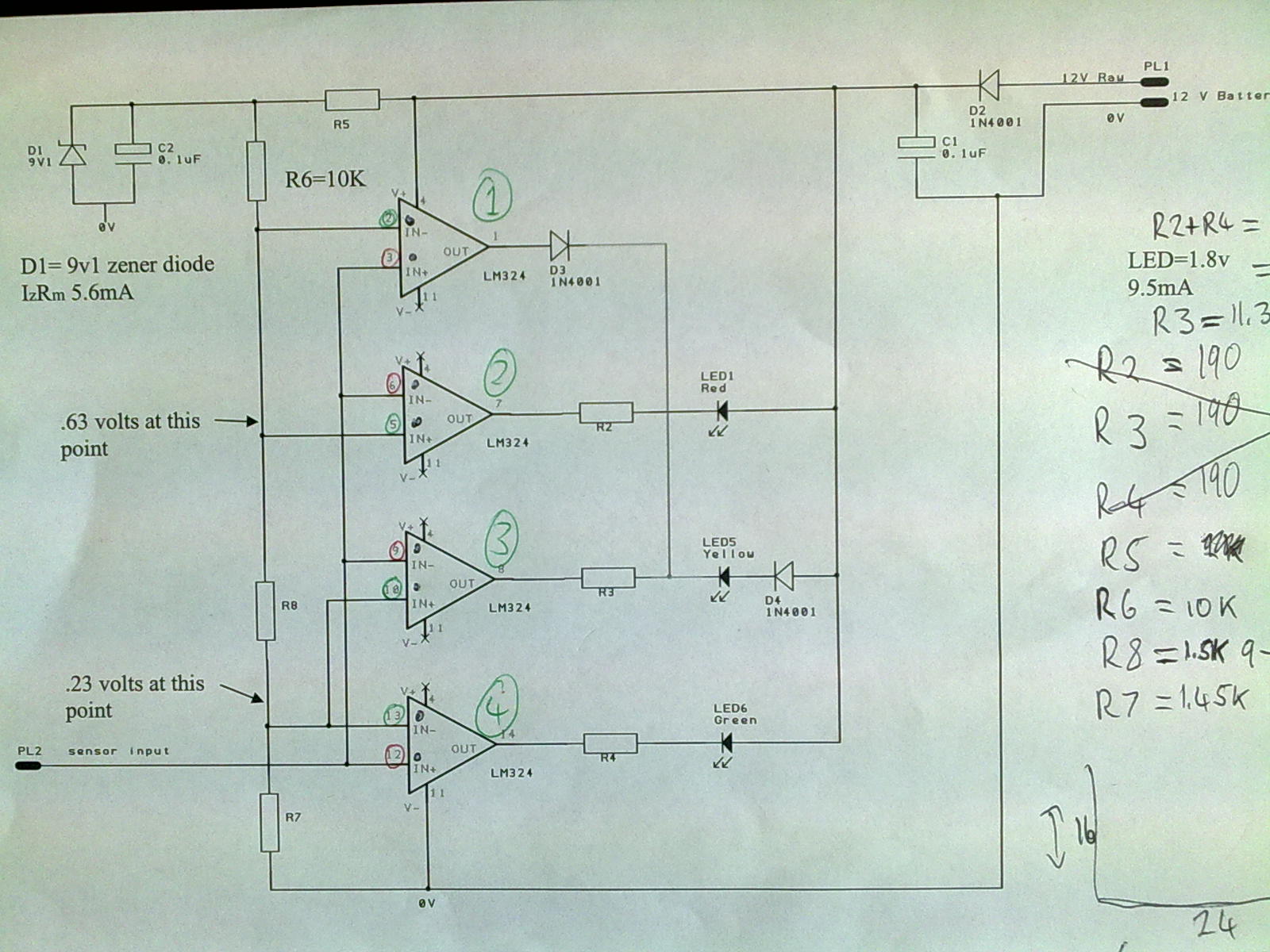
A 12V power supply is connected to the positive terminal, allowing current to flow through a protection diode and a capacitor that smooths the voltage. A zener resistor (R5) limits the current to the zener diode, which regulates the...
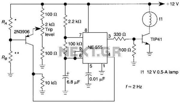
A sensor activates transistor Q1 to turn on the low-frequency 555 oscillator, which generates pulses to control LAMP II. The sensor may respond to variations in light or temperature. Either resistor RA or RB can function as the sensor,...
This circuit is a motion detection sensor that utilizes a light source and detector as an infrared motion detector. The motion sensor employs an infrared LED and a phototransistor. Since it relies on light, the sensor's sensitivity can be...

This design idea explains how to develop a water sensor circuit that can monitor upper and lower water levels. The water sensor circuit is designed to detect and monitor water levels within a specified range, providing feedback when the water...