
Window-comparator

A window detector is a specialized comparator circuit designed to detect the presence of a voltage between two prescribed limits, which defines a voltage window. This circuit is constructed by logically combining the outputs of two single-ended comparators using IN914 diodes. When the input voltage is between the upper limit, VuL, and the lower limit, VLL, the output voltage is zero; otherwise, it reaches a logic high level. The output of this circuit can be utilized to drive a logic gate, LED driver, or relay driver circuit. The circuit illustrated in Figure 16-1 demonstrates a 2N2222 NPN transistor being activated by the window comparator. When the input voltage to the window comparator falls outside the range established by the VuL and VLL inputs, the output transitions to a positive state, which activates the transistor and illuminates the LED indicator.
The window detector circuit operates by comparing the input voltage against two reference voltages, VuL and VLL, which define the acceptable voltage range. The two comparators within the circuit are configured to output signals based on whether the input voltage exceeds these limits. The use of IN914 diodes allows for the logical combination of these outputs, ensuring that the output remains low (zero volts) only when the input voltage is within the specified window.
When the input voltage exceeds the upper limit, VuL, or drops below the lower limit, VLL, the output of the circuit transitions to a high state. This output can be used to control various electronic components. For instance, the output can drive a logic gate to perform further logical operations, energize an LED driver to provide visual feedback, or activate a relay driver to control larger loads.
In the specific implementation shown in Figure 16-1, the output of the window comparator is connected to the base of a 2N2222 NPN transistor. When the output switches to a high state due to the input voltage being outside the defined window, the transistor is turned on. This allows current to flow from the collector to the emitter, thereby powering an LED indicator. The LED serves as a visual indication of the condition of the input voltage, providing immediate feedback to the user regarding whether the voltage is within the acceptable range.
This circuit configuration is particularly useful in applications where monitoring voltage levels is critical, such as in battery management systems, over-voltage protection circuits, or in various automation systems where maintaining voltage within specific limits is essential for proper operation.A window detector is a specialized comparator circuit designed to detect the presence of a voltage between two prescribed limits; that is, within a voltage window. This circuit is implemented by logically combining the outputs of two single-ended comparators by the IN914 diodes.
When the input voltage is between the upper limit, VuL. and the lower limit, VLL, the output voltage is zero; otherwise it equals a logic high level. The output of this circuit can be used to drive a logic gate, LED driver, or relay driver circuit. The circuit shown in Fig. 16-1 shows a 2N2222 npn transistor being driven by the window comparator. When the input voltage to the window comparator is outside the range set by the VuL and I"LL inputs, the output changes to positive, which turns on the transistor and lights the LED indicator.
Related Circuits
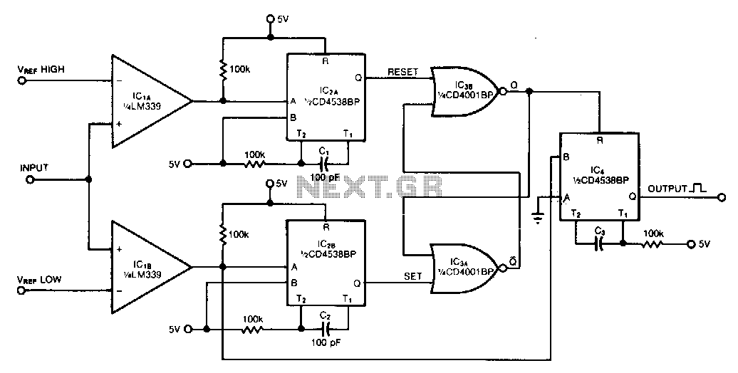
This window comparator generates an output pulse for each event that occurs within a specified window. Each output pulse signifies an input voltage pulse or level change that exceeds VREFLOW but not VREFHIGH. The monostable multivibrators, IC2A and IC2B,...