
Window-comparator

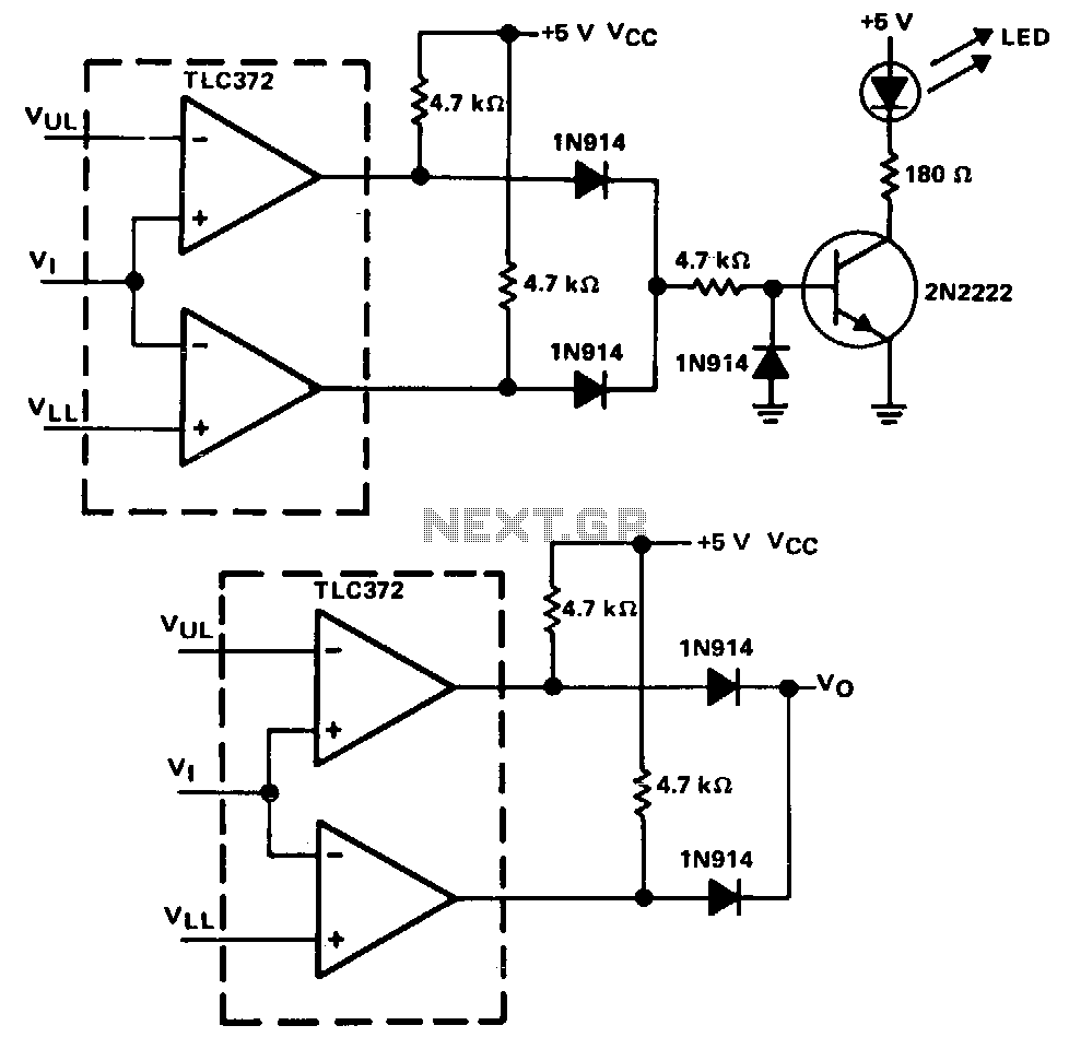
This window comparator generates an output pulse for each event that occurs within a specified window. Each output pulse signifies an input voltage pulse or level change that exceeds VREFLOW but not VREFHIGH. The monostable multivibrators, IC2A and IC2B, produce a 10 µs pulse at their Q output in response to a rising edge at their A input. Comparator IC1B produces a rising edge when the input exceeds VREFLOW, and comparator IC2A produces a rising edge when the input exceeds VREFHIGH. The NOR gates, IC3A and IC3B, form a bistable latch whose Q output, when low, disables IC4. IC4, unless disabled, produces output pulses in response to falling edges at the IC1B comparator output. The width of these pulses is determined by selecting the value of C3. The circuit can handle an input waveform containing 0 to 2 V amplitudes and 10 Hz to 10 kHz frequency components.
The window comparator circuit is designed to generate output pulses corresponding to input voltage events that fall within a specific voltage range, defined by two reference voltages, VREFLOW and VREFHIGH. The operational principle relies on the behavior of two monostable multivibrators (IC2A and IC2B) which are configured to output a pulse of 10 microseconds duration when triggered by a rising edge at their input.
Comparator IC1B is responsible for detecting when the input voltage exceeds the lower reference level (VREFLOW), generating a rising edge that signals the event. Similarly, comparator IC2A detects when the input voltage surpasses the upper reference level (VREFHIGH), also generating a rising edge. The interaction between these components determines whether the output pulse is produced, effectively creating a window within which input voltage changes are acknowledged.
Furthermore, the circuit includes NOR gates (IC3A and IC3B) that create a bistable latch configuration. This latch maintains its state until a specific condition is met—when the Q output is low, it disables the subsequent component, IC4. IC4 is designed to produce output pulses triggered by falling edges from the output of comparator IC1B, thus ensuring that the output pulses are generated only under the right conditions.
The pulse width generated by IC4 is adjustable by changing the capacitance value of capacitor C3, allowing for flexibility in application based on the desired timing characteristics. The circuit is capable of handling input waveforms with voltage amplitudes ranging from 0 to 2 volts and frequency components between 10 Hz and 10 kHz, making it suitable for various low-frequency signal processing applications.This window comparator generates an output pulse for each event that occurs within a specified window. That is, each output pulse signifies an input voltage pulse or level change that exceeds VREFLOW. but not VREFHIGH· The monostable multivibrators, IC2A and IC2B, produce a 10-l"s pulse at their Q output in response to a rising edge at their A input.
Comparator IC1B produces a rising edge when the input exceeds VREF Low and comparator IC2A produces a rising edge when the in])ut exceeds VREFHIGH.· The NOR gates, IC3A and IC3B, form a bistable latch whose Q output, when low, disables IC4. IC4, unless disabled, produces output pulses in response to falling edges at the IC1B comparator output. You set the width of these pulses by selecting the value of C3. The circuit can handle an input waveform containing 0 to 2 V amplitudes and 10-Hz to 10-kHz frequency components.
Related Circuits
A window detector is a specialized comparator circuit designed to detect the presence of a voltage between two prescribed limits, which defines a voltage window. This circuit is constructed by logically combining the outputs of two single-ended comparators using...