
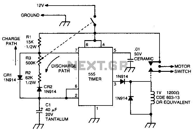
Windshield wiper hesitation control unit
The 555 timer in astable mode operates by continuously switching between its high and low states, generating a square wave output. In this configuration, the timing cycle is defined by the resistors and capacitor connected to the timer. The formula for calculating the frequency (f) of the oscillation is given by:
\[ f = \frac{1.44}{(R1 + 2R2) \cdot C1} \]
Where:
- R1 is the resistor connected between the discharge pin (pin 7) and Vcc.
- R2 is the resistor connected from the threshold pin (pin 6) to the discharge pin (pin 7).
- C1 is the timing capacitor connected between the threshold pin (pin 6) and ground.
The duty cycle, which determines the proportion of time the output is high versus low, is influenced by R2 and R3, particularly the potentiometer used for adjustment. When the potentiometer is varied, it changes the resistance in the circuit, thereby altering the timing intervals. The minimum time delay, when R3 is at zero ohms, is established by R2, ensuring that the circuit operates within the desired timing range.
In practical applications, this circuit can be employed in various timing and delay scenarios, such as in light flashers, timer circuits, and sound generators. The ability to adjust the timing with a potentiometer provides flexibility for different requirements, making this circuit versatile in electronic designs. Proper selection of the capacitor and resistor values is essential for achieving the desired oscillation frequency and duty cycle.This circuit uses the 555 timer in the asta-ble or oscillatory mode. The length of time the timer is off is a function of the values of CI, R2, and R3. The potentiometer which controls the amount of "hesitation" (Approximately 2 to 15 seconds) R2 provides a minimum time delay when R3 is at its zero ohms position. 🔗 External reference
Related Circuits

A bidirectional H-bridge DC motor control circuit is illustrated. The circuit utilizes the L298 integrated circuit from ST Microelectronics. The L298 is a dual full-bridge driver that supports a wide operating voltage range and can manage load currents up...
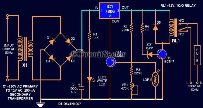
This circuit automates the control of street or porch lights. The automatic lamp controller circuit utilizes a 7806 voltage regulator IC, which can be employed to automate street lights, tube lights, or any other home electrical lighting systems. The...
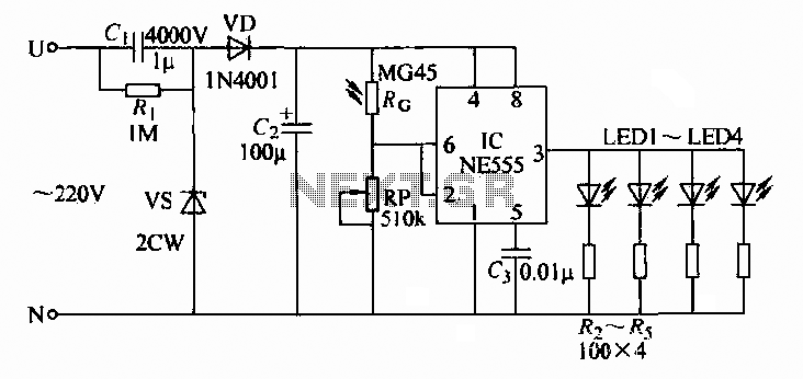
A 220V AC input is converted to a DC operating voltage of approximately 3.3V using a capacitive G buck regulator, a rectifier diode (VD), and a filter capacitor connected to an NE555 integrated circuit (IC). The IC functions as...
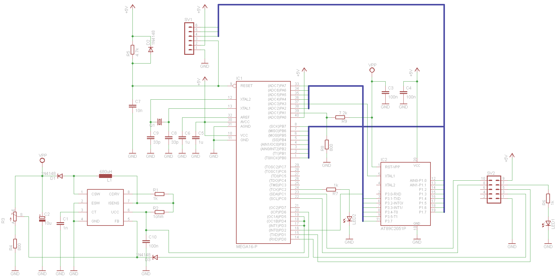
This project has been set aside for several years. It was initially intended for programming old 8051 microcontrollers, which have since become obsolete. The project was recently revisited due to the need for a programmer for the Atmel Xmega...
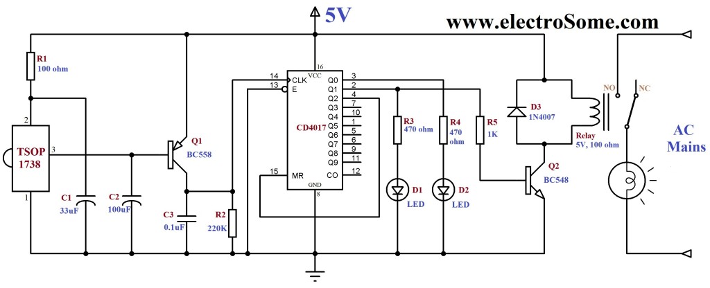
An infrared (IR) remote control circuit for managing home appliances can be constructed using a Decade Counter CD4017, a 555 Timer, and a TSOP1738 infrared receiver. This circuit allows users to control home devices with a standard remote control,...
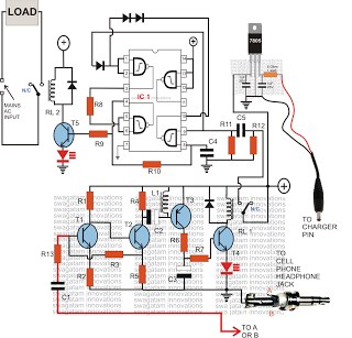
Control any electrical device from anywhere in the world using a cell phone, without incurring costs for individual commands. This system allows operation of various appliances, such as vehicles, doors, and air conditioners, with a simple button press on...