
gsm based cell phone controlled remote

The described system utilizes a GSM modem cell phone to control various electrical devices remotely. The architecture comprises a control circuit connected to a relay that interfaces with the appliances. Upon receiving a call from a pre-assigned number, the modem cell phone generates a ringtone, which is detected by the control circuit. This circuit is designed to interpret the ringtone signal and activate the relay, thereby switching the connected load either ON or OFF based on the owner's command.
The circuit design includes essential components such as a relay driver, which can be a transistor or an opto-isolator, to ensure safe operation of the relay. The relay itself should be rated appropriately for the load it will control, whether it is a light bulb, motor, or other appliances. Additionally, a power supply circuit is necessary to provide the required voltage and current to the control circuit and the modem cell phone.
The inclusion of a charger module is vital for maintaining the modem cell phone's battery life. This module should be compatible with the cell phone's charging specifications, ensuring that the battery is kept at an optimal charge level for continuous operation.
To enhance the system's reliability, it is advisable to implement features such as a status LED indicator, which can provide visual feedback on the operational state of the connected load. Furthermore, a fuse or circuit breaker should be integrated to protect against overload conditions.
Overall, this GSM-based remote control system represents a versatile solution for managing household and automotive appliances, leveraging existing cell phone technology to create a cost-effective and user-friendly interface. Proper planning and execution of the schematic design will result in a functional and efficient remote control system.You can control any electrical gadget from any part of the world through your cell phone, that too without spending a penny for the individual commands. Whether it`s you vehicle, your basement door, your mansion gate or simply the air conditioner of your house, everything can now be switched by just a flick of your cell phone button.
And mindyou, it`s completely fool proof, meaning no false triggering is possible through any other cell phone signals, it works only through the owners cell phone commands. All domestic electrical appliances like, lights, fans, motors, TV sets, refrigerators, Air conditioners, washing machine, porch lights, garage door, house gate, basement gate or entrance, car ignition, car doors, water heater etc.
The concept has been already discussed in one of my previous articles How to make a GSM car security system, and the going about is unbelievably simple. The unit discussed here is a universal device and can be used for operating all types of electrical gadgets from any part of the globe, just by making a single blank call to the systems number.
The system will faithfully respond to every call made from your cell phone and will alternately switch the connected load ON and OFF as per your instructions. This cell phone acts as a modem and is permanently attached with the internal control circuit of the unit.
The modem cell phone is initially made ready by putting a SIM card inside it and by configuring the essential assigned numbers into its phone directory. These assigned numbers are the only numbers to which this modem responds. Therefore you would want to assign only those numbers through which you may like to make a call to the system .
For safety reasons more than one number is assigned to the modem so that in case one of your cell phones is out of order or has low battery, you always have the option of using the other cell phone for triggering the system. The biggest advantage of the design is that, any cheap NOKIA cell phone can be used here as the modem and therefore there`s no fear of the modem becoming obsolete.
A simple yet effective cell phone remote control switch details has been discussed here with complete schematics and step by step tutorial. If you have sufficient prior knowledge of electronics, you should be making this complete unit within a days time.
Lets begin the discussion. This entire unit now becomes the receiver unit. The modem cell phone NOKIA1280 is assigned with desired numbers, for example the owners cell number and a few other numbers of the owners family members. When the modem cell phone is called through these assigned numbers, the modem ring tone becomes active and this ring tone is applied to the control circuit and is processed for operating a relay and the connected load.
Since the modem cell phone needs to be attached permanently inside the switching unit, it needs to be charged at regular intervals so that it remains functional all the time. For this, a separate cell phone charger module has also been incorporated along with the maincircuitwhich keeps the modem cell phone battery always up to date and fully charged.
You will have first get or procure the following materials or parts for making this unit. I would suggest not to make the Printed board initially, it would better to first test the working over a general board and if thing goes then you would want to transfer it over a well designed P-C-B. 🔗 External reference
Related Circuits
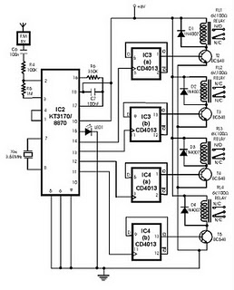
This project utilizes DTMF (dual-tone multi-frequency) signals, commonly used in telephones for dialing digits, as control codes. The DTMF tones are employed for frequency modulation of the carrier signal. At the receiver unit, these frequency-modulated signals are intercepted to...
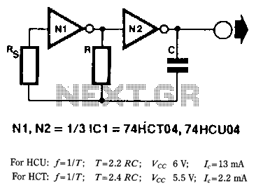
When frequency stability is not of primary importance, a simple yet reliable digital clock oscillator can be constructed using relatively few components. High-speed CMOS (HCU/HCf) inverters or gates with an inverter function are particularly suitable for creating such oscillators...
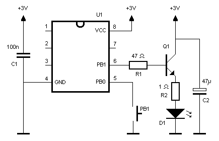
An infrared (IR) remote control designed for a Nikon DSLR camera. While not essential, it serves as an interesting project. The protocol used by the original Nikon remote controls ML-L1 and ML-L3 is straightforward, as explained by Big Mike...
In order to achieve a status between two levels of switching for two calls at the same time, you must first establish privacy on each call. Otherwise, you will end up with all four phones talking to each other,...
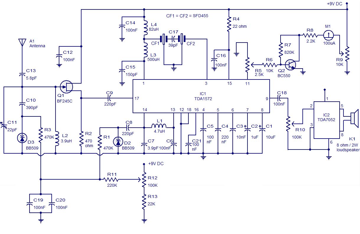
High-quality AM radio circuit based on the TDA1572 IC. The AM radio receiver circuit operates from 9V DC and has a 1W output power. It requires a minimum number of external components. The AM radio circuit utilizing the TDA1572 integrated...
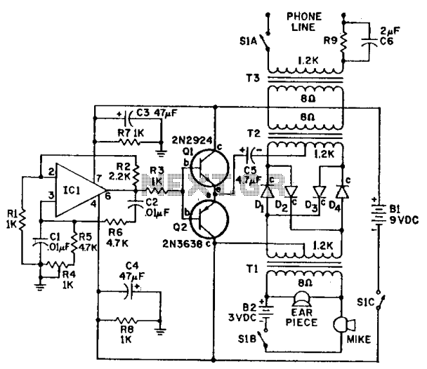
IC-1 and the associated circuitry form a stable audio tone generator that feeds a buffer amplifier, Q1 and Q2. The tone output is taken from the emitters of the transistor pair to supply a carrier voltage for a balanced...