
Wireless am microphone

If L1 is disturbed, it may be necessary to readjust L2 to maintain peak performance. The audio sensitivity from the microphone can be enhanced by reducing the value of resistor R10, depending on the microphone's impedance, and vice versa.
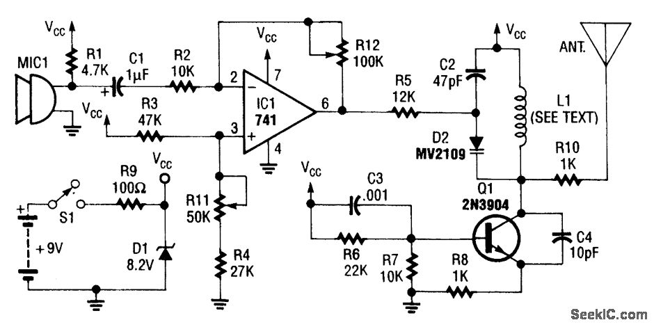
The circuit involves a tunable RF oscillator utilizing transistor Q1, which generates the RF signal. This signal is then modulated by transistor Q2, which is driven by an amplified audio signal from operational amplifier IC1. The operational amplifier is configured to increase the audio signal's amplitude, ensuring that it effectively modulates the RF carrier wave.
Resistor R4 plays a critical role by coupling the amplified audio signal to the base of the modulator transistor Q2, allowing for efficient modulation of the RF signal. The tuning elements, inductors L1 and L2, are crucial for adjusting the frequency response of the oscillator. L1 is primarily responsible for tuning the circuit to the desired frequency range, while L2 is used for fine-tuning and optimizing the output signal's amplitude.
When setting up the circuit, it is essential to adjust the AM radio to an unused frequency within the specified range. This ensures that the radio receives the modulated signal without interference from other broadcasts. The adjustment of L1 should be performed carefully to observe changes in the audio level, indicating that the circuit is correctly tuned.
In cases where L1 is disturbed or modified, re-tuning L2 may be necessary to restore peak performance, ensuring that the modulated signal is at its optimal level. Additionally, the circuit's overall performance can be influenced by the microphone's impedance. Therefore, adjusting the value of resistor R10 can enhance audio sensitivity, allowing for better modulation quality, depending on the specific characteristics of the microphone used in the application.Transistor Ql and its associated components comprise a tuneable rf oscillator. The rf signal is fed to transistor Q2, the modulator. Operational amplifier ICl increases the audio signal and applies it through resistor R4 to the base of Q2. Tune an AM radio to an unused frequency between 800 to 1600 kHz. Tune Ll for a change in the audio level coming from the radio. Peak the output by adjusting L2 If Ll is disturbed, it may be necessary to readjust L2 for peak performance. Depending on the impedance of the microphone audio sensitivity can be increased by decreasing the value of RIO and vice versa.
Related Circuits
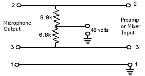
These devices require power to operate. This power can be supplied by a battery inserted into the microphone, a separate dedicated power supply with a specialized multi-pin cable, or most commonly, phantom power. Phantom power is supplied by a...
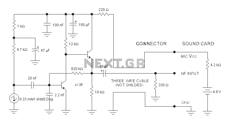
The sound card for a PC typically includes a microphone input, speaker output, and occasionally line inputs and outputs. The microphone input is specifically designed for dynamic microphones, accommodating an impedance range of 200 to 600 ohms. An adaptation...
The page is about equipping an Atmel AVR microcontroller based system with a Prism WLAN interface. This document is intended for people that already have experiences with the AVR microcontrollers and teaches them how to add a cheap but...
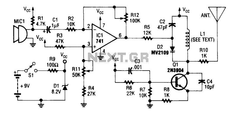
An operational amplifier integrated circuit (741) amplifies the audio signal from microphone MIC1, with resistor R12 adjusting its gain. The amplified audio is directed to the oscillator circuit, which includes transistor Q1 and associated components. D2 is a varactor...
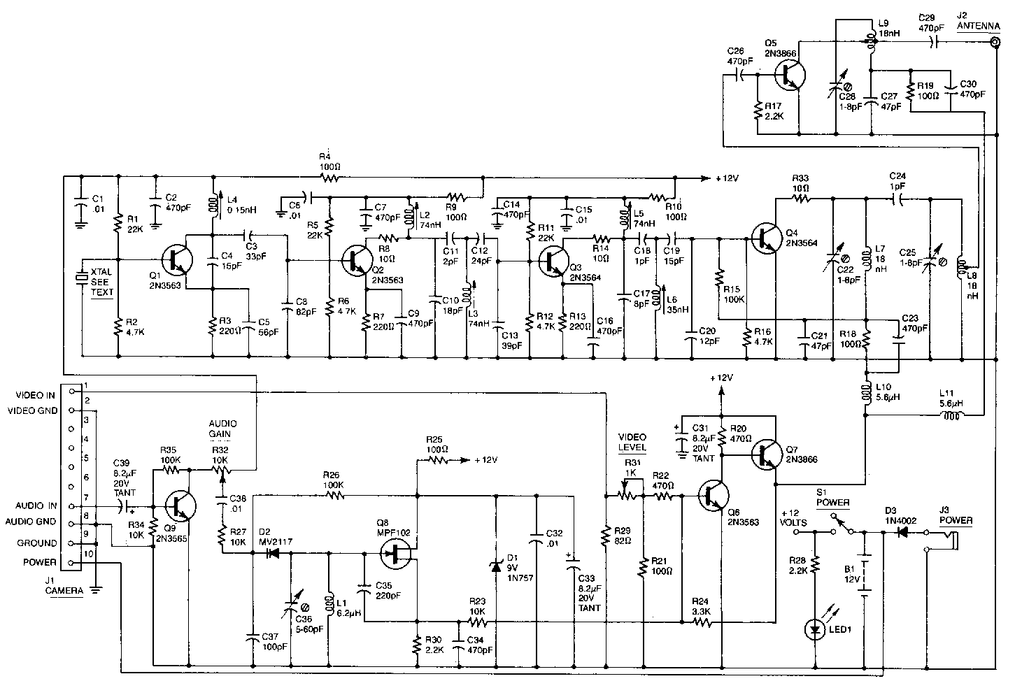
This high-performance video camera link transmits signals from a video camera to a VCR or from a VCR to TVs throughout a home. The initial stage of the RF chain features a crystal-controlled oscillator, Q1, operating at a frequency...
An operational amplifier integrated circuit (741) amplifies the audio signal from microphone 1 (MIC1), with resistor R12 determining its gain. The amplified audio signal is then directed to the oscillator circuit, which includes transistor Q1 and associated components. D2...