
FM transmitter microphone
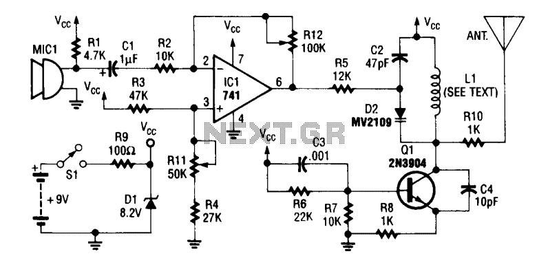
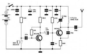
The circuit utilizes the operational amplifier (op-amp) 741, which is a versatile device commonly used in audio applications due to its high gain and low noise characteristics. The microphone (MIC1) captures audio signals, which are then sent to the op-amp for amplification. The gain of the op-amp is set by resistor R12, allowing for customization based on the required output level.
The amplified audio signal is then fed into an oscillator circuit, which is primarily composed of transistor Q1. This transistor is responsible for generating a carrier frequency that can be modulated. The modulation process is accomplished using D2, the varactor diode, which changes its capacitance based on the input audio signal. This change in capacitance alters the frequency of the oscillator, resulting in frequency modulation (FM) of the output signal.
Inductor L1, constructed with three turns of #18 gauge wire, plays a crucial role in the oscillator circuit by providing the necessary inductance to work in conjunction with the varactor diode. The choice of wire gauge and the number of turns are critical for achieving the desired inductance value, which impacts the overall performance of the oscillator.
The antenna, designed as a 12-inch whip, is used to transmit the modulated signal. The length of the antenna is selected to optimize transmission efficiency at the operating frequency, ensuring that the signal can be effectively radiated into the surrounding environment. Overall, this circuit design is suitable for applications requiring audio transmission via frequency modulation, providing a compact and efficient solution for wireless audio communication.An op-amp IC (741) amplifies the audio signal from MIC1, and R12 controls its gain. Audio is fed to the oscillator circuit Q1 and related components. D2 is a varactor diode. Audio fed to D2 causes FM of the oscillator signal. L1 is 3 turns of #18 wire. The antenna is a 12" whip. 🔗 External reference
Related Circuits
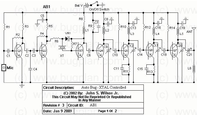
This circuit operates between 150 to 165 MHz. The crystals used are Digi-Key Electronics Barrel Crystals of the CA-301 type, which are relatively inexpensive. Any fundamental crystal with a frequency between 14 and 17 MHz can produce an output...
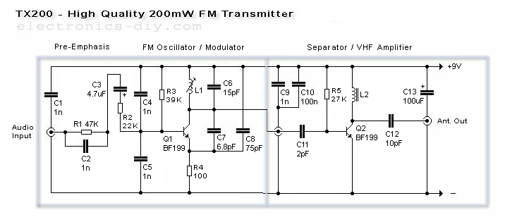
The TX200 is an advanced and significantly larger VFO/VCO FM transmitter, recognized as one of the best transmitters available. It is a 200mW FM transmitter designed for stereo PLL applications, providing a wide range for broadcasting music throughout a...
This oscillator is known as the Colpitts oscillator and is voltage-controlled to facilitate frequency modulation (FM) and phase-locked loop (PLL) control. The transistor T1 should be a high-frequency (HF) transistor for optimal performance; however, in this instance, a common...
This schematic represents an FM transmitter that delivers an output power of 3 to 3.5 watts, operational within the frequency range of 90 to 110 MHz. While the stability of the circuit is acceptable, incorporating a Phase-Locked Loop (PLL)...
Simple FM Transmitter Circuit This simple FM transmitter circuit was built using a transistor with a transmission distance of about 300m around your home. The simple FM transmitter circuit utilizes a transistor to modulate audio signals onto a radio frequency...
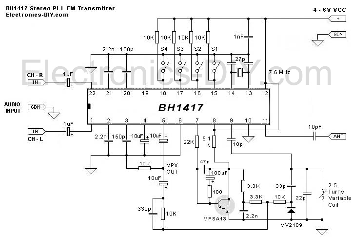
This is the latest BH1417 FM Transmitter design from RHOM that includes a lot of features in one small package. It comes with pre-emphasis, limiter so that the music can be transmitted at the same audio level, stereo encoder...