
Wireless-fm-microphone

Utilize standard RF wiring precautions. Optimal speech clarity is achieved by employing an electret microphone. For music reproduction, replace it with a dynamic microphone element.
In the design of audio circuits, particularly those involving speech and music, the choice of microphone is crucial for achieving the desired sound quality. An electret microphone is preferred for speech applications due to its high sensitivity and excellent frequency response, which enhances clarity and intelligibility. This type of microphone operates on a built-in FET (Field Effect Transistor) that requires a bias voltage, typically supplied through a resistor connected to the power source.
In contrast, for music reproduction, a dynamic microphone is recommended. Dynamic microphones utilize a diaphragm attached to a coil of wire placed within a magnetic field. When sound waves hit the diaphragm, it moves, generating an electrical signal proportional to the sound wave. This design is robust and can handle high sound pressure levels, making it suitable for musical instruments and live performances.
When designing circuits that integrate these microphones, it is essential to implement standard RF (radio frequency) wiring precautions. This includes proper grounding techniques, the use of shielded cables to minimize electromagnetic interference, and maintaining appropriate distances from RF sources. These practices help ensure that the audio signal remains clear and free from unwanted noise, thereby enhancing the overall performance of the audio system.
In summary, the selection of microphone type—electret for speech and dynamic for music—coupled with adherence to RF wiring standards, is vital for optimizing audio clarity and fidelity in electronic circuit designs.Use standard rf wiring precautions. The best speech clarity is obtained by using an electret microphone. For music reproduction, substitute a dynamic mike element. 🔗 External reference
Related Circuits

Transistor Q1 functions as an amplifier for the condenser microphone MIC1. The output from Q1 is fed to the base of transistor Q2 through a 4.7 µF capacitor. Capacitors C2 and L1 form an LC tank circuit, which is...
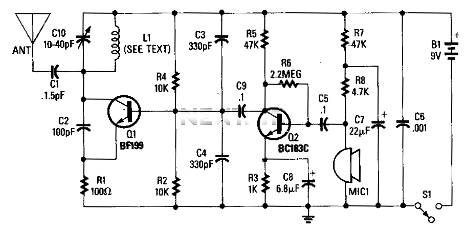
An adjustable capacitor C10 and a coil L1 create a tank circuit that, along with Q1, C2, and R1, oscillates at a frequency within the FM band. The center frequency is adjustable by tuning C10. An electret microphone, M1,...