
Wireless/Wii Hack for SNES and NES Controllers
Surprisingly, the NES controller has a lot more space a vailable inside which generally makes it easier to fit the various components. The PIC controller is somewhat problematic, however, as there is not enough space to fit both the chip and PCB inside. In fact, the space is so thin that there isn`t even room to add a PIC by itself. In general you have three choices: · Place the PIC on its side to the far edge of the controller, so that the edge of the PCB passes in between the pins, and solder all wires directly to the pins.
I personally chose the last option, but any of them should work fine. The only other main difference is a small change in the firmware that you need to program the PIC, as the NES controller returns buttons is a slightly different order. The circuit schematic for the NES controller is basically identical to that of the SNES transmitter, although the pin numbers and colors on the original NES controller are slightly different to the SNES controller.
There have been plenty of reports of non-official hardware using different schemes, so I strongly recommend using a multi-meter first to determine which pins map to which wires. The circuit schematic for the version of this hack that uses the official NES controller is as follows: The NES controllers return data in a slightly different format to the SNES controllers, and therefore require different firmware.
The receiver expects a data pack in a format similar to that returned by the SNES controller, so the NES controller firmware needs to rearrange the data to match this format and set all non-SNES bits to 0. The NES firmware is as follows: The circular extrusion at B should also be removed. It usually keeps the back-plate separated from the PCB, but we`ll need to make room for the battery later on.
There is a small plastic pin at C that passes through the PCB and slightly extrudes out the other side. The tip of this tab needs to be removed to make room for the battery, but it should not be removed altogether.
Place the PCB back into the front plate to see how much it pokes through and then cut that little bit off, but leave enough so that the PCB is still held securely. It might be a bit difficult figuring out exactly what to do here from the photo alone, but if you put the PCB back into the front plate and then try to position the battery on top of it then it`ll be obvious what you need to do.
Next install a 2. 5mm mono recharge socket in the hole where the cable used to come out. A 2. 5mm LED should be installed to the left of the socket and a slider switch should be installed on the right. The diode and resistor should also be installed by soldering them directly to the component pins: As with the SNES controller, the slider switch and recharge socket have been glued into place, although the NES controller is thinner than the SNES controller so the switch doesn`t need a sliver of PCB to prop it up.
The transmitter chip and crystal should now be installed in the front plate. A little bit of care should be taken here, as there are plenty of metal contacts on the PCB that they can short against. I wrapped the components in heat-shrink, but electrical tape would work just as well. Just be sure to solder wires to the relevant pins so that they can be routed to the other side of the PCB and connected to the PIC and battery: This isn`t exactly the most secure way of installing the PIC, but it works.
The pins of the chip need to be bent out so that the back-plate can be replaced later this also makes it a little easier to solder wires to them. The back-plate forms a reasonably sung fit which I relied upon to hold 🔗 External reference
Related Circuits
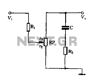
Figure 1-87 illustrates an effective loudness volume control circuit that employs a standard potentiometer. The components used are minimal, yet the performance is notably impressive. The operation principle is as follows: when the internal impedance of the source is...
The heart of the Chloroplast is the Motorola MC34164-3 Micro power Undervoltage Sensing Circuit (U1 in the following diagram). In normal use, this component monitors the voltage at pin 2, and applies a ground at pin 1 (out) when...
Application note on designing linear and switch-mode (switching DC-DC converter current source) battery charger applications that require external microcontrollers and related system-level issues for notebook computers. The application note provides guidance on the design of both linear and switching DC-DC...
Most telephone security devices available in the market are simple yet quite expensive. These devices typically provide blinking or beeping indications of line-tapping or misuse but often do not guarantee protection against unauthorized operations. A unique and straightforward circuit...
The electronics consist of three op-amp circuits; each built around one half of an NE5532 dual op-amp. Each circuit uses that op-amp in a different configuration. The first circuit is a non-inverting pre-amp, the second is a unity-gain phase-inverter,...
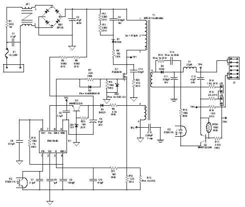
A high brightness LED evaluation board has been developed using the Fairchild Semiconductor FAN7554D PWM controller. The evaluation board for high brightness LEDs incorporates the Fairchild Semiconductor FAN7554D PWM controller, which is designed to provide efficient power management and precise...