
Active Noise-Canceling Headphones
The signals from the microphone then go to ICl-a, an NE5532 set up as a standard non-inverting pre-amp. The gain is set to one plus the ratio of R8/R6 in the feedback path. The total gain for that stage is about 31 dB. Resistor R4 provides a ground reference for the pre-amp. A pair of high-pass filters is formed by C2/R4 and C4/R6. Those filters block any DC that tries to slip through the pre-amp.
From the output of the pre-amp, the microphone signal is sent down two different paths. It feeds both one pole of Sl-a and the phase-inverter. The phase inverter is nothing more than a second NE5532 configured as a unity-gain inverting op-amp (IC2-a). The output of IC2-a is connected to the other pole of Sl-a. That way, Sl-a can select either the inverted or the non-inverted signal. The selected signal on Sl-a’s common pole goes to potentiometer R14-a. That potentiometer sets the level of the microphone signal feeding the headphone amplifier.
The headphone amplifier is built around IC3-a, a third NE5532 wired as an inverting op-amp stage. The gain here is set by the ratio of R19/R15. That type of op-amp configuration can be easily modified to add a summing feature by the inclusion of R17. The second input comes from an auxiliary line-level input that is attenuated by potentiometer R23-a.
There is a reason why 10K-ohms was chosen for the value of R15 and R17. Besides keeping the values of R19 manageable, the 10K-ohm resistors interact with the 100K-ohm linear potentiometers. The potentiometers then behave in a logarithmic fashion.
This is how that feature works: One end of the potentiometer is tied to ground because it is used as a voltage divider. Because the summing junction of an op-amp is at a virtual ground, the 10K-ohm resistor is also essentially tied to ground. That affects the response of the potentiometer. As the potentiometer is rotated, there is a more pronounced increase in the output as the end of the potentiometer’s travel is reached. That causes a smooth increase in perceived loudness of the signal. Potentiometers with an audio taper are available, but a linear-taper unit is easier to obtain and costs less.
The output of the headphone amplifiers is coupled to output jack J3 through R21. That resistor provides overload protection to IC3-a in case the output is shorted. The NE5532 will supply a 10-volt rms signal into a 600-ohm load with very little distortion, translating to approximately 166 mW of power. Most personal stereos typically supply only 20 to 30 mW of power to headphones.
A final note on using operational amplifiers as headphone amplifiers: Most generic ones will not supply enough current to function properly. Substitutes for the NE5532 that are known to work include the OP275 from Analog Devices, the OPA2604 from Burr Brown, and the LM833 from National Semiconductor. These components are available from several sources, including Digi-Key, Allied Electronics, and Jameco.
Construction. There are two parts to this project: building the electronics and modifying a pair of headphones. The circuit is relatively simple and can easily be assembled on a perfboard. One style of perfboard that simplifies construction is one having a pre-etched copper pattern on its solder side that connects groups of holes together. One example of that type of perfboard is Radio Shack #276-150.
The etched pattern on that board has a pair of buses that run the length of the board, which are very convenient for power distribution. When using that type of board for the Noise-Canceling Headphones, it is advisable to start by spacing out the three ICs on the board so that they straddle the buses. Then, attach the power supply leads from each chip to the buses. The remainder of the circuit can be wired point-to-point. The electronics consist of three op-amp circuits; each built around one half of an NE5532 dual op-amp. Each circuit uses that op-amp in a different configuration. The first circuit is a non-inverting pre-amp, the second is a unity-gain phase-inverter, and the third is an inverting headphone amplifier.
Since the Noise-Canceling Headphones is a stereo device, the circuit is actualty two identical circuits side-by-side. Only one channel will be described; the second channel works in exactly the same way. The schematic diagram in Fig. 1 shows the design of the electronics portion of the project. A headset-mounted microphone is connected to J1, a 1/8-inch stereo jack. Electret-condenser microphones need a 2- to 10-volt bias voltage for their internal FET pre-amps. That is supplied by R2. A voltage-dividing network, which also decouples the bias volt-age from the power supply, is provided by Rl and Cl. That is necessary due to the high gain of the entire signal chain. The signals from the microphone then go to ICl-a. an NE5532 set up as a standard non-inverting pre-amp. The gain is set to one plus the ratio of R8/R6 in the feedback path. The total gain for that stage is about 31 dB. Resistor R4 provides a ground reference for the pre-amp. A pair of high-pass filters is formed by C2/R4 and C4/R6. Those filters block any DC that tries to slip through the pre-amp. From the output of the pre-amp, the microphone signal is sent down two different paths. It feeds both one pole of Sl-a and the phase-inverter. The phase inverter is nothing more than a second NE5532 configured as a unity-gain inverting op-amp (IC2-a).
The output of IC2-a is connected to the other pole of Sl-a. That way, Sl-a can select either the inverted or the non-inverted signal. The selected signal on Sl-a’s common pole goes to potentiometer R14-a. That potentiometer sets the level of the microphone signal feeding the headphone amplifier. The headphone amplifier is built around IC3-a, a third NE5532 wired as an inverting op-amp stage. The gain here is set by the ratio of R19/R15. That type of op-amp configuration can be easily modified to add a summing feature by the inclusion of R17. The second input comes from an auxiliary line-level input that is attenuated by potentiometer R23-a. There is a reason why 10K-ohms was chosen for the value of R15 and R17. Besides keeping the values of R19 manageable, the 10K-ohms resistors interact with the 100K-ohm linear potentiometers.
The potentiometers then behave in a logarithmic fashion. This is how that feature works: One end of the potentiometer is tied to ground because we are using it as a voltage divider. Because the sum-ming junction of an op-amp is at a virtual ground, the 10K ohm resistor is also essentially tied to ground.
That affects the response of the potentiometer, As the potentiometer is rotated, there is a more pronounced increase in the output as the end of the potentiometer’s travel is reached. That causes a smooth increase in perceived loudness of the signal. Potentiometers with an audio taper are, of course, available, but a linear-taper unit is easier to obtain and costs less.
The output of the headphone amplifiers is coupled to output jack J3 through R21. That resistor provides overload protection to IC3-a in case the output is shorted. If you have never used an op-amp for driving headphones before, you are in for a nice surprise. The NE5532 will supply a 10-volt rms signal into a 600-ohm load with very little distortion. That works out to 166 mW of power. Most personal stereos only supply 20 to 30 mW of power to headphones. A final note on using operational amplifiers as headphone amps: Most generic ones will not supply enough current to function properly. Some substitutes for the NE5532 that are known to work include the 0P275 from Analog Devices, the OPA2604 from Burr Brown, and the LM833 from National Semiconductor.
Those components are available from several sources, including Digi-Key, Allied Electronics, and Jameco. Construction. There are two parts to this project: building the electronics and modifying a pair of headphones. The circuit is relatively simple and can easily be assembled on a perfboard. One style of perfboard that simplifies construction is one having a pre-etched copper pattern on its solder side that connects groups of holes together.
One example of that type of perfboard is Radio Shack #276-150. The etched pattern on that board has a pair of buses that run the length of the board. Those buses are very convenient for power distribution. If you use that type of board for the Noise-Canceling Headphones, it is best to start by spacing out the three ICs on the board so that they straddle the buses. Then attach the power supply leads from each chip to the buses. It is then a simple matter of point-to-point wiring the rest of the circuit. 🔗 External reference
Related Circuits
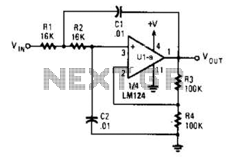
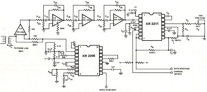
The circuit presented has a cutoff frequency of approximately 1 kHz. The resistors R1, R2, and capacitors C1, C2 can be adjusted to achieve any desired frequency. The circuit is designed as a filter, likely a low-pass or high-pass filter,...
Eight months and eighteen days ago, on March 25, a request was received via email for a commissioned piece of electronic clothing similar to a DJ jacket for a musical performer to wear on stage. After some consideration, the...
The tube headphone amplifier in figure 1 is a high current mu follower, with a 12AU7 cathode follower driven by a 6CG7. Both sections of each tube are paralleled to minimize noise. It's a zero global feedback, OTL design...
This application note aims to introduce filter designers to the basics of active filter design using monolithic integrated circuit operational amplifiers (op-amps). It includes a table of transfer functions and network equations for high-pass, low-pass, band-pass, and band-reject filters....
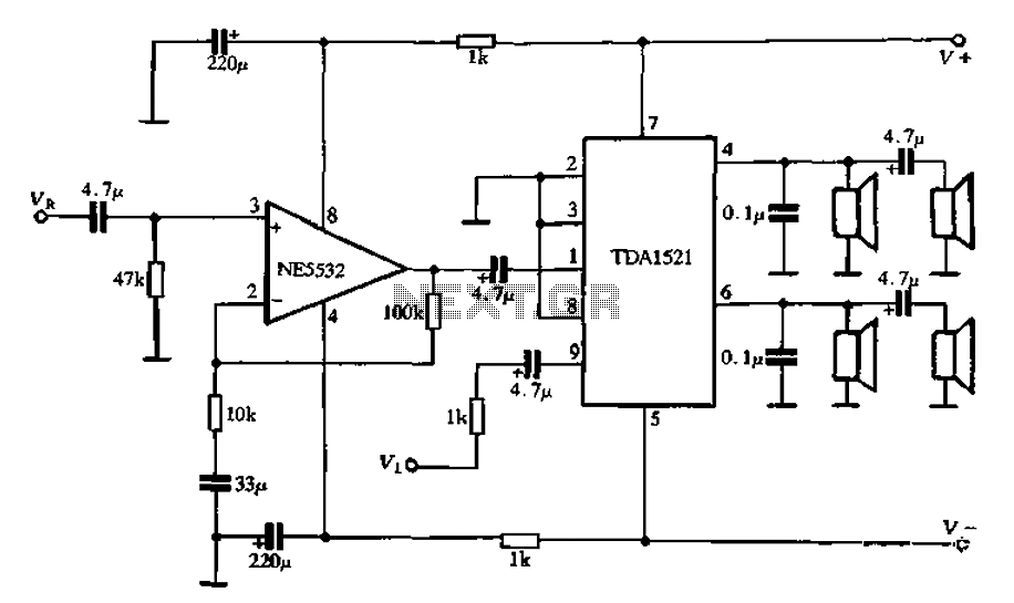
Active speaker with amplifier circuit TDA1521 and NE5532, featuring dual-channel input and dual-channel output. The active speaker circuit utilizes the TDA1521 integrated circuit, which serves as the power amplifier. This IC is designed for high-efficiency amplification, providing a robust output suitable...
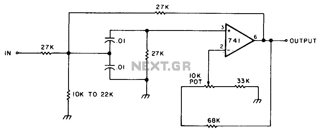
This circuit features adjustable bandwidth with a center frequency of approximately 800 Hz. A 10 kΩ potentiometer is used to adjust the bandwidth, varying from approximately ±350 Hz to ±140 Hz at the 3 dB down points. The circuit operates...