
With NE555 make double touch light switch 1

The circuit utilizes the NE555 timer in a monostable configuration, where the output state is determined by the duration of the input pulse generated by the touch electrodes. The touch-sensitive feature is achieved through capacitive coupling, which allows the human body to act as an additional capacitor, generating a small signal that can be detected by the NE555's trigger input. The half-wave rectifier circuit, composed of diodes and capacitors, converts the AC voltage to DC, ensuring stable operation of the timer circuit.
When the On electrode M1 is touched, the capacitive coupling creates a transient voltage that triggers the NE555. The output at pin 3 goes high, activating the SCR, which remains latched on until the circuit is reset. The LED indicator provides visual feedback that the circuit is active, enhancing user experience.
To turn off the light, the off electrode M2 is touched, which sends a similar transient signal to the threshold input of the NE555. This resets the timer, pulling the output low and turning off the SCR, which cuts power to the light. The design ensures that the circuit operates safely at 220V AC, with components rated appropriately to handle the voltage and current levels involved.
Overall, this touch-sensitive light switch circuit is an efficient and user-friendly solution for controlling lighting, utilizing simple components to achieve a reliable and effective design.3-2, the circuit by the touch electrode, when integrated with the base NE555 made double touch light switch circuit shown in Figure composition circuit and the triac circuit of several parts. 220V AC simple capacitive buck by Cl, C2, VDI, VD2 composition of the half-wave rectifier voltage regulator circuit, power at both ends of C2 obtained after about 12V DC voltage of about timebase circuit for electricity. Turn on the lights when needed, just to touch the On electrode sheet Ml, human induced noise signal injected into the base of the trigger circuit A Pin 2, so that the time base circuit is set, the output of 3 feet high output, Thus obtained positive trigger SCR vs current opening, lights H powered light, this time also will be working status LED light indication switches.
Turn off the lights when needed, just to touch the off electrode sheet M2. Human body induced noise signal is injected into the base when the threshold circuit terminal 6 feet, immediately reset A time base circuit, the output of 3-pin output low. vs loss of trigger current, when the AC zero crossing that is turned off, the lamp H goes out and the LED will go out.
Related Circuits
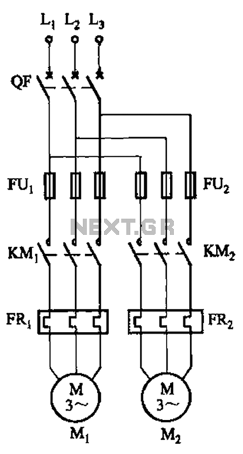
The circuit illustrated in Figure 3-64 operates with switch SA1 in the work position and switch SA2 in the standby position, allowing motor Mi to run while motor Mz remains on standby. In the event of downtime for motor...

A digital red light jump checking system with an RF transmitter. This project allows for the tracking of vehicles that run red lights by capturing their license plate numbers and the time of the violation. The digital red light jump...

Many analog ohm meters have a non-linear scale, which results in poorer resolution at higher resistance values. This is due to the use of inexpensive current sources. Many analog ohm meters operate on a principle where the scale is not...
4QD manufactures motor speed controllers, and all their H bridges utilize PWM. This is a simple switch circuit designed for reversing and stopping a motor without speed control. Two inputs, A and B, control the bridge. When both inputs...
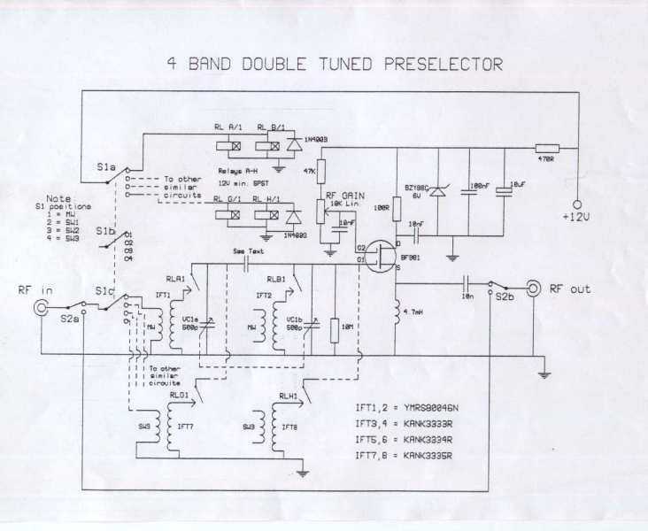
Once again, this is a project designed by David Sayles. The input can be from a longwire or a loop antenna. The unit covers MW and Sw to 30MHz. This project involves a versatile antenna interface designed to accommodate...
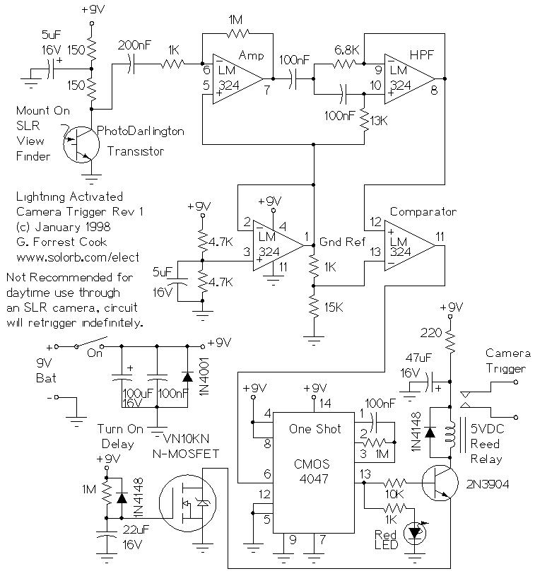
Lightning Activated Camera Shutter Trigger. This picture was taken using the circuit. This circuit is used to trigger a camera's electronic shutter circuit when a flash occurs. The Lightning Activated Camera Shutter Trigger is designed to capture images of lightning...