
H bridge switch for small motors
The motor control circuit described utilizes a half-bridge configuration to achieve basic motor control functions, specifically forward, reverse, and off states. The inputs A and B provide a straightforward interface for controlling the motor's operation. When both inputs are high, the circuit effectively disables the motor by connecting both terminals to ground (0V), ensuring no current flows through the motor windings.
The activation of Tr2 by setting input A low allows the current to flow in a direction that drives the motor forward. In contrast, activating Tr6 by setting input B low reverses the current flow, thus reversing the motor's direction. This simple control mechanism is effective for applications where precise speed control is not required.
The half-bridge configuration operates using complementary Darlingtons, which enhances the current handling capabilities and provides a robust switching solution. The inclusion of Tr1 as the input to the top Darlington transistor replaces the conventional pull-up resistor, streamlining the design and potentially improving response times.
The absence of provisions for recirculating motor currents when the switch is turned off is a notable design choice. While this may not pose issues for small motors due to their lower energy release, it is advisable to consider adding flywheel diodes to manage inductive kickback effectively. These diodes can protect the transistors from voltage spikes that occur when the motor is de-energized, thereby prolonging the lifespan of the components.
The selection of transistors is critical for the circuit's performance. The use of 2N3053 and BC214 transistors in the original design illustrates the importance of choosing components that can handle the required current and voltage levels. It is essential to ensure that the transistors selected can switch the motor safely and efficiently to prevent overheating or failure during operation.
Overall, this motor control circuit provides a fundamental yet effective solution for applications requiring simple motor direction control without the complexity of speed regulation.4QD manufacture motor speed controllers so all our H bridges are PWM. Here`s a simple switch circuit for reversing and stopping a motor without any control of speed. Two inputs, A and B, control the bridge. With both high (or open circuit) both ends of the motor are connected to 0v. Connect A low and Tr2 turns on causing the motor to go forward. C onnect B low and Tr6 turns on, reversing the motor. If A and B are both low, both ends of the motor are high, so the motor is off. Another way of looking at he half bridge is as a totem-pole output stage, with both transistors as complementary darlingtons. The resistor which would normally pull up the base of the top of th pole is replaced by Tr1 which forms also the input to the top-of-the-pole darlington.
Note that no provision is made for recirculating motor currents at switch off. Since the motor is relatively small, the energy at switch off is small and as the circuit is not switching at a high rate, the dumped energy is small, so the breakdown energy in the transistors is not a problem. However - you may like to put reverse parallel flywheel diodes across the transistors. In the original TO5 transistors were used: 2N3053 for the even numbers and BC214 for the odd numbers.
The circuit`s nice in that respect - it uses NPN power transistors and PNP drivers in each section of the bridge. You have to chose transistors that will safely switch your motor. We aim to transmit more information by carrying articles. Please send us an E-mail to wanghuali@hqew. net within 15 days if we are involved in the problems of article content, copyright or other problems.
We will delete it soon. 🔗 External reference
Related Circuits
A reader named Andrea ([email protected]) submitted a circuit designed for educational purposes. The primary objective is to demonstrate how to electronically toggle an output state using only a push-button switch. According to Andrea, this simple circuit can drive a...
Light Switch. This is a light switch or light-activated relay circuit. The relay activates when the light-dependent resistor (LDR) is uncovered and deactivates when the LDR is covered. It is adjustable for sensitivity and includes an LED indicator. This light-activated...
This is a lamp timer capable of operating two separate relay switches. Outputs can be in three (or restricted to two) states: OFF, delayed ON and constant ON. Delayed ON mode is indicated by the LEDs. The source code...
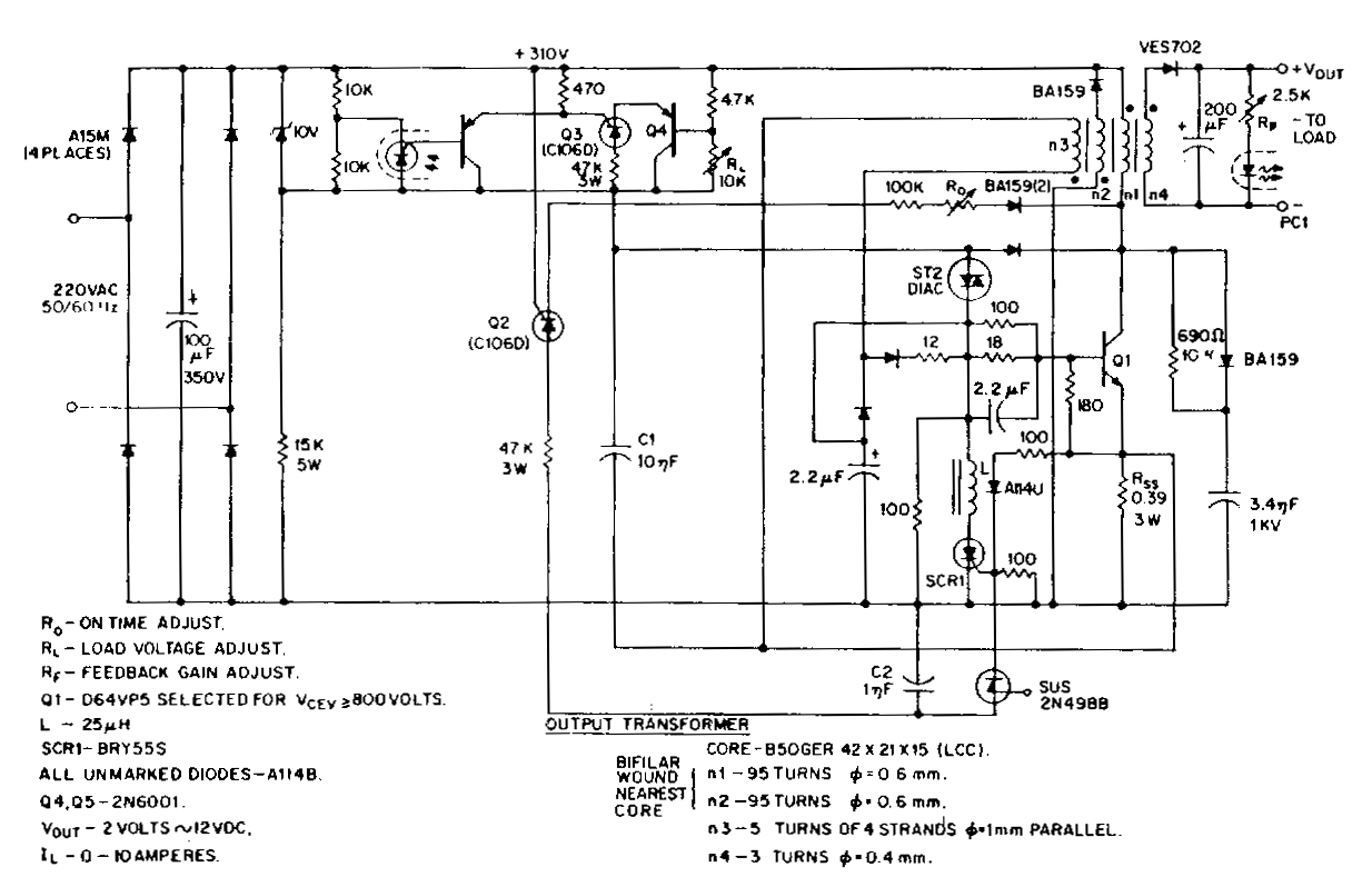
This low-voltage, high-current output switching power supply operates from a 220 VAC input. In this circuit, an ST2 diac relaxation oscillator, along with Q3, C1, and the diac, initiates the conduction of the output switching transistor Q1. The on-time...
This 5-volt Switch Mode Power Supply circuit utilizes an integrated circuit (IC) from National Semiconductor, which specializes in the production and design of ICs for switch-mode power supply applications. The 5-volt Switch Mode Power Supply (SMPS) circuit is designed to...
The semiconductor thermistor is an embedded thermal protection element that is sensitive to temperature, with a temperature error of 5 degrees. It offers reliability, a small size (diameter 3.5 mm), and ease of installation, making it suitable for embedding...
Warning: include(partials/cookie-banner.php): Failed to open stream: Permission denied in /var/www/html/nextgr/view-circuit.php on line 713
Warning: include(): Failed opening 'partials/cookie-banner.php' for inclusion (include_path='.:/usr/share/php') in /var/www/html/nextgr/view-circuit.php on line 713