
Xbee Wireless Interface Circuit
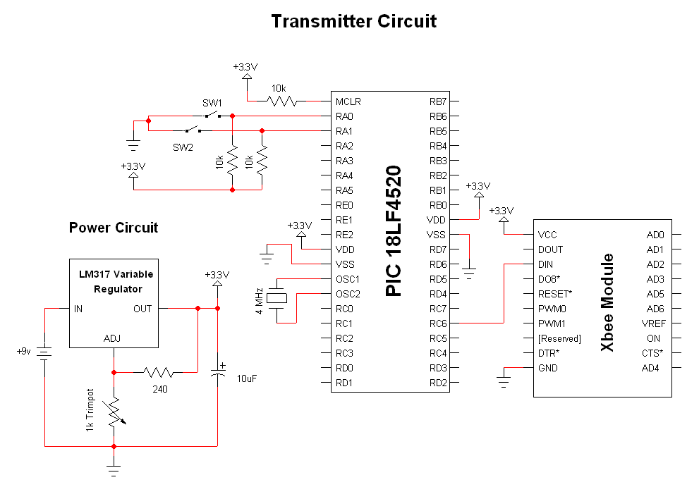
The Xbee modules serve as the primary communication interface, enabling wireless data transmission between the transmitter and receiver circuits. The PIC 18LF452 microcontroller, known for its versatility, is used in both circuits to manage operations and data processing. The LM317 voltage regulator ensures that both circuits operate within the specified voltage range, providing a stable +3.3V output necessary for reliable performance. The choice of a 10µF capacitor for noise filtering is critical, as it helps mitigate voltage fluctuations and maintains a stable power supply to the microcontroller and Xbee modules.
In the transmitter circuit, the integration of two buttons allows for user input, which is essential for initiating data transmission. The use of a pull-up resistor ensures that the microcontroller can accurately detect button presses, translating them into digital signals that can be wirelessly transmitted. The connection of PortB pin 0 to the Xbee Din pin is crucial for sending data to the receiver, highlighting the importance of proper pin assignments in microcontroller interfacing.
Conversely, the receiver circuit is designed to output received data through an LED, providing a visual indication of successful data reception. The connection of PortB pin 0 to the Xbee Dout pin allows the microcontroller to read the incoming data stream, which can then be processed or displayed as needed. This setup exemplifies a simple yet effective wireless communication system, leveraging the capabilities of the Xbee modules and the PIC microcontroller to facilitate seamless data exchange in various applications.The great thing about these little Xbee modules is they take care of almost all the heavy lifting. As you can see below both the transmitter and the receiver circuits are drop-dead simple. The main devices used in the circuit are the Xbee Modules, PIC 18LF452 and LM317. Both circuits use the same simple power regulation circuit with the LM317 f or +3. 3v reg. An output capacitor of 10uF is used for noise filtering which helps keeps the output DC signal stable around +3. 3v. A 1k or 5k trimmer is used with a 240ohm resistor to create the adjustable voltage to the required +3.
3v The transmitter circuit has the standard PIC 18LF4520 power, ground, MCLR and crystal connections. In addition to the normal connections, two buttons are connected to PORTA pins 0 and 1. A pull up resistor of 10k © is used so that the digital input seen is +5v or logic 1. When either button is pressed, the input is connected to ground/+0v making the input a logic 0. PortB pin 0 is connected to the Xbee Din pin. This is for the wireless data to be output to the receiver. The receiver circuit has the same standard PIC power, ground, MCLR and crystal connections. The difference between the transmitter is instead of input via buttons, we are showing output with an LED.
Similarly, the PORTB pin 0 is connected to the Dout pin of the Xbee module so that the wirelessly transmitted information can be received. 🔗 External reference
Related Circuits

Electronic FM Telephone Transmitter Schematic. The following schematic design illustrates a circuit diagram for an FM telephone transmitter built on a compact PC board layout. This small design allows it to be easily integrated within the housing of a...
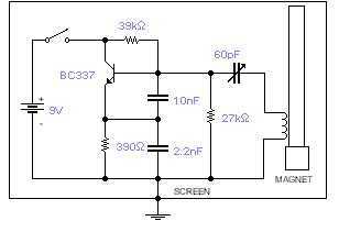
This basic oscillator will detect the Earth magnetic field. The ferrite rod and coil are taken from an old Medium Wave receiver and a small magnet is glued at one end. Tune to a medium wave commercial station until...
High-quality, discrete component design for input and tone control modules to complement the 60-watt MOSFET audio amplifier with a high-quality preamplifier design. The circuit design focuses on creating a high-fidelity audio preamplifier that enhances the performance of a 60-watt MOSFET...

The Class A power amplifier exhibits low distortion; however, it suffers from low efficiency and limited output power, prompting the design of Class B power amplifier circuits. The Class B amplifier operates by shifting the operating point of the...

This circuit is designed to automatically adjust the brightness of lights based on the ambient light intensity. In bright conditions, the lights remain off, while in low ambient brightness, the lights are activated. The circuit incorporates a thyristor (VT1)...
The two circuits below illustrate using the 555 timer to close a relay for a predetermined amount of time by pressing a momentary N/O push button. The circuit on the left can be used for long time periods where...
Warning: include(partials/cookie-banner.php): Failed to open stream: Permission denied in /var/www/html/nextgr/view-circuit.php on line 713
Warning: include(): Failed opening 'partials/cookie-banner.php' for inclusion (include_path='.:/usr/share/php') in /var/www/html/nextgr/view-circuit.php on line 713