
Zero crossing detector: do I really need the 7W resistor
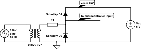
Zero crossing detection is a critical function in various electronic applications, particularly in controlling AC loads and ensuring efficient power management. The objective is to create a reliable system that accurately detects the point where the AC waveform crosses zero volts, allowing for precise control of power to the load.
The schematic provided utilizes a combination of resistors and potentially optocouplers to achieve this detection. The generation of a square wave signal indicates that the circuit successfully identifies the transitions between the positive and negative half-cycles of the AC waveform. However, the choice of resistor is crucial, as a high resistance value can lead to significant power dissipation, resulting in thermal issues. This necessitates careful consideration of the resistor's power rating and the overall thermal management of the circuit.
In terms of voltage handling, components must be rated adequately for voltages exceeding 400V, which is typical in mains applications. While using a transformer to step down the voltage is a viable solution, it introduces size and cost constraints that may not be acceptable for all designs. Alternative methods, such as using high-voltage resistors or specialized voltage dividers, may be explored to mitigate these concerns.
When selecting an optocoupler for this application, several characteristics should be considered: the input and output voltage ratings, the isolation voltage, and the switching speed. The optocoupler must be capable of handling the expected input conditions while providing sufficient isolation to protect sensitive components in the controller. Additionally, the driving current of 30mA should be evaluated in terms of its necessity; if the optocoupler can function effectively at lower currents, this could reduce power consumption and heat generation within the circuit.
In summary, the design of a zero crossing detection circuit requires careful consideration of component ratings, thermal management, and overall circuit efficiency. Exploring various approaches, such as resistive methods, transformer use, and optocoupler characteristics, will yield a more robust and effective solution for the intended application.Provide zero crossing detection to my controller. Using the schematic below, I managed to generate square wave signal, representing positive v/s negative half-period. The problem is that the resistor needs to be quite large : Quite the heater. Also, voltage rating above 400V is required. I realize that a transformer could be used to step down the mains voltage. However, those guys tend to be bulky and rather expensive. Any recomendations I found some nice explanations on Hardware deign and noise suppression on the site. stevenvh`s answer looks especially promising on calculating the resistor value. So let`s keep my question more general. What are the approaches - resistor, transformer, others. What characteristics are desired in the optocoupler Is the chosen driving current (30mA) huge and unnecessary
🔗 External reference
Related Circuits
Unfortunately, there is no breadboard available for testing; however, modifications can be made to the PCB. The 1K potentiometer has been removed until the strobe functionality can be established. The circuit in question appears to involve a strobe light mechanism,...
The circuit above is a canonical AC coupled common emitter amplifier, which is typically used as a linear amplifier rather than a switch that activates when the input exceeds a certain level. The AC coupled common emitter amplifier is...
This project is designed for a custom-made battery casing that provides ample space for concealing components. The switch can be adapted for various projects but is specifically tailored to meet e-bike requirements. It utilizes a clever thyristor functionality to...
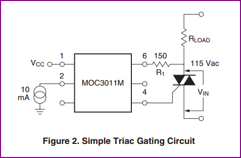
A small circuit is being constructed to control a 200W heater using a MOC3023 optoisolator and a BT136 triac. The datasheet for the optotriac suggests a specific circuit configuration. The inquiry pertains to the determination of the 180-ohm resistor...
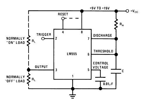
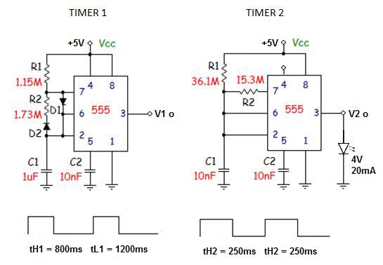
The old 555 timer will work based on the specifications provided, and it is a suitable choice if this is the exact problem to be addressed. As mentioned by Steven, this type of timing block is generally referred to...
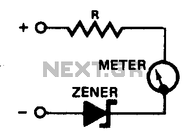
A zener diode placed in series with a voltmeter will prevent the meter from reading until the applied voltage exceeds the zener voltage. Thus, a 10-volt zener in series with a 5-volt meter will allow the condition of a...