
Need help with strobe circuit

The circuit in question appears to involve a strobe light mechanism, which typically requires precise timing and control signals. The removal of the 1K potentiometer suggests that it was previously used to adjust the intensity or frequency of the strobe effect. In the absence of a breadboard for prototyping, direct modifications to the PCB will be necessary to test and refine the strobe functionality.
To achieve the desired strobe effect, the circuit may incorporate a 555 timer IC configured in astable mode. This configuration allows the circuit to oscillate between high and low states, creating a pulsing effect suitable for strobe lighting. The frequency of the strobe can be adjusted by changing the resistors and capacitors connected to the 555 timer.
In addition to the 555 timer, a transistor may be included to drive the strobe light. The transistor acts as a switch, allowing for higher current to flow through the strobe light than what the timer can provide. A suitable NPN transistor, such as the 2N2222, could be used for this purpose, with the base connected to the output of the 555 timer through a current-limiting resistor.
Power supply considerations are also critical; the circuit should be designed to operate within the voltage ratings of the components used, typically powered by a DC source. Proper decoupling capacitors should be placed near the power pins of the IC to ensure stable operation.
In summary, while the absence of a breadboard poses challenges for testing, modifications to the PCB can facilitate the development of the strobe circuit. The focus should be on optimizing the timing components, ensuring reliable switching through the transistor, and providing adequate power supply stability.Unfortunately I don`t have a breadboard to try this out on but can modify the PCB. I`ve removed the 1K pot till I can get the strobe working and than.. 🔗 External reference
Related Circuits
A truly timeless circuit. The LM317 is a versatile and highly efficient 1.2-37V voltage regulator that can provide up to 1.5A of current with a large heat sink. It is ideal for just about any application. This was the...
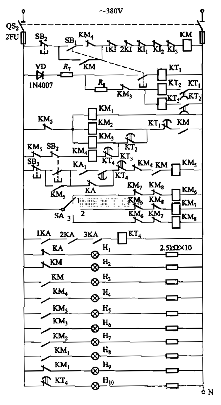
The circuit is illustrated. A motor utilizes series resistance in the rotor winding for starting. The drawing includes electrical velocity off the relay KIi ~ KI3 for motor short circuit protection and overcurrent. Additionally, relays 1KI and 2KI provide...

FIG IC, ICR, Ri, R, and AN composition form a bistable contact circuit with a Ge transistor. It includes components such as ICc, lc, c2, and Dj, and is associated with a one-shot delay circuit. The circuit can be...
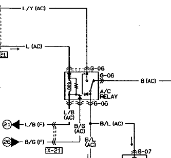
An automotive relay is being analyzed, which exhibits a more complex wiring configuration than typical relays. The diagram indicates that the B/G line maintains a high signal if certain conditions are met, specifically when the engine temperature is excessively...

The LM1877 is a stereo amplifier designed to deliver 2W per channel into 8-ohm loads. It is intended to operate with a minimal number of external components, making it a versatile integrated circuit suitable for various audio amplification applications,...

The circuit consists of four 2-input NAND gates and a CMOS CD4011 type 555 timer, allowing for either a static or high-time period output while maintaining minimal power consumption. Additionally, the circuit features a 3-door and 4-door composition RS...