
Zero Feedback Headphone Tube Amplifier

It is possible to make the turns ratio such that the output impedance of the amplifier is much smaller than the load. Power transfer is not optimum, but the output valve is tending to run under constant current conditions which has the advantage of lowering distortion.
The output power will depend on the impedance of the headphones; the amp gives about 10 V output before clipping. The gain of the output stage is 0.33, so quite a bit of amplification is needed before it. I am a fan of SRPP because it improves linearity, lowers output impedance and allows for a large voltage swing. The first stage uses a double triode directly coupled to the output valve, giving an overall gain of about 20 dB. The circuit is shown in figure 1. The 12B4A cathode resistor tends to run quite hot so use a 7 W component here.
There is no feedback from the output to the input. The gain can be increased slightly by decoupling the cathode of the SRPP input, or alternatively try a ni-cad battery bias. Although I use the 6072A for this stage, suitable alternatives are the 5965 and 12AT7. The 12AT7 is slightly less linear. The 6922 can also be used with a change to the heater wiring but the gain will be lower. The input phono jacks are located round the back, along with the umbilical between power supply unit and the amplifier. The Switchcraft headphone jack is on the front (left) next to the volume control (right). The plan was to have a gold-plated Switchcraft jack, which I saw at an AES show, but I could not get hold of one, so it is a standard tin-plated Switchcraft.
The amplifier should work with headphone impedances as low as 32 ohms; I have tried lower impedance Sennheisers and they seem OK. I would be worried at less than 10 Ohms or so. The sound quality of the amplifier is excellent. The lack of feedback produces an open natural, detailed sound without any of the harshness sometimes experienced with solid state amplifiers. I can now listen in bliss well into the night when other members of the household have gone to sleep! This is definitely one of my best projects.
I have only given the power rating of resistors which dissipate any appreciable power. For all others, 0.5 W resistors will do. The capacitors came from all over the place. The 1600uF big one was second hand in a junk shop; the others from HAM fests. The 2.2 K Ohms resistor on the output of the audio transformers is there to give the output valve some load if the headphones are disconnected. Without it, the transformer can ring off load. The output impedance of the amp is so low that its value is quite uncritical.
The amplifier design employs a high step-down transformer ratio of 20:1 to achieve low output impedance, essential for driving headphones with varying impedances, including those lower than 300 Ohms, such as the HD600. The output stage utilizes the 12B4A valve with a specified anode impedance of approximately 1000 Ohms, resulting in a calculated output impedance of around 2.5 Ohms, categorizing it as notably low for a valve amplifier. This low impedance is advantageous for headphone compatibility, allowing for optimal performance across a range of headphone impedances.
In terms of transformer design, the turns ratio is crucial for maintaining the desired output impedance while ensuring that the amplifier operates efficiently. This is particularly important in audio applications where impedance matching can significantly affect sound quality and power transfer. Although maximum power transfer principles are typically applied to loudspeakers, headphone operation does not necessitate strict adherence to these conditions due to the relatively low power levels involved.
The output power available from the amplifier is contingent upon the connected headphone impedance, with a maximum output voltage of approximately 10 V before clipping occurs. The output stage gain is configured at 0.33, necessitating considerable amplification prior to reaching clipping levels. The use of a SRPP (Shunt Regulated Push-Pull) configuration in the first stage enhances linearity and reduces output impedance, facilitating a larger voltage swing, which is beneficial for audio fidelity.
Components such as the 12B4A cathode resistor are specified to handle higher power ratings (7 W) due to thermal considerations. The absence of feedback in the circuit design contributes to a natural and open sound quality, mitigating distortion, and enhancing the listening experience.
Alternative valve options for the first stage include the 6072A, 5965, and 12AT7, with the latter offering slightly less linear performance. The design accommodates various input configurations, with phono jacks positioned at the rear and a Switchcraft headphone jack at the front for user convenience.
The amplifier is capable of driving headphones with impedances as low as 32 Ohms, with satisfactory performance noted even at lower impedance values, although caution is advised below 10 Ohms. The overall sound quality is described as detailed and natural, distinguishing it from solid-state amplifiers known for harshness.
In terms of component specifications, only resistors dissipating significant power are rated explicitly, while others can be of lower power ratings (0.5 W). The capacitors used in the circuit are sourced from various locations, contributing to the overall design's flexibility. The inclusion of a 2.2 K Ohm resistor at the output of the audio transformers serves to load the output valve appropriately, preventing ringing when headphones are disconnected, which is critical for maintaining circuit stability. The overall design philosophy emphasizes low output impedance and high fidelity, ensuring a quality listening experience across a range of headphone impedances. To get a low output impedance I needed to use quite a high step-down ratio (20:1); after all, the amplifier may be used with headphones of lower impedance that the 300 Ohms of the HD600. The output valve is the 12B4A which has a anode impedance of about 1000 Ohms, so the output impedance of the amplifier is about 2.5 Ohms, which is very low for a valve amplifier.
You can use other valves here but watch that the anode impedance is not too high or the output impedance and bass-cut off frequency will both rise. It is usual with power amplifiers to match the impedance of the loudspeaker to the impedance of the anode circuit using the equation turns ratio = square root (impedance ratio).
Under these conditions, maximum power transfer takes place from the amplifier to the load. With headphones, the power involved is so small that it is not necessary to operate under such conditions. It is possible to make the turns ratio such that the output impedance of the amplifier is much smaller than the load. Power transfer is not optimum, but the output valve is tending to run under constant current conditions which has the advantage of lowering distortion.
The output power will depend on the impedance of the headphones; the amp gives about 10 V output before clipping. The gain of the output stage is 0.33, so quite a bit of amplification is needed before it. I am a fan of SRPP because it improves linearity, lowers output impedance and allows for a large voltage swing.
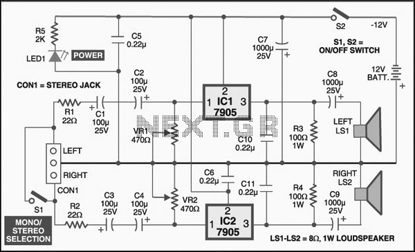
The first stage uses a double triode directly coupled to the output valve, giving an overall gain of about 20 dB. The circuit is shown in figure 1. The 12B4A cathode resistor tends to run quite hot so use a 7 W component here. There is no feedback from the output to the input. The gain can be increased slightly by decoupling the cathode of the SRPP input, or alternatively try a ni-cad battery bias.
Although I use the 6072A for this stage, suitable alternatives are the 5965 and 12AT7. The 12AT7 is slightly less linear. The 6922 can also be used with a change to the heater wiring but the gain will be lower. The input phono jacks are located round the back, along with the umbilical between power supply unit and the amplifier. The Switchcraft headphone jack is on the front (left) next to the volume control (right). The plan was to have a gold-plated Switchcraft jack, which I saw at an AES show, but I could not get hold of one, so it is a standard tin-plated Switchcraft.
The amplifier should work with headphone impedances as low as 32 ohms; I have tried lower impedance Sennheisers and they seem OK. I would be worried at less than 10 Ohms or so. The sound quality of the amplifier is excellent. The lack of feedback produces an open natural, detailed, sound without any of the harshness sometimes experienced with solid state amplifiers.
I can now listen in bliss well into the night when other members of the household have gone to sleep! This is definitely one of my best projects. I have only given the power rating of resistors which dissipate any appreciable power. For all others, 0.5 W resistors will do. The capacitors came from all over the place. The 1600uF big one was second hand in a junk shop; the others from HAM fests. The 2.2 K Ohms resistor on the output of the audio transformers is there to give the output valve some load if the headphones are disconnected.
Without it, the transformer can ring off load. The output impedance of the amp is so low that its value is quite uncritical. 🔗 External reference
Related Circuits
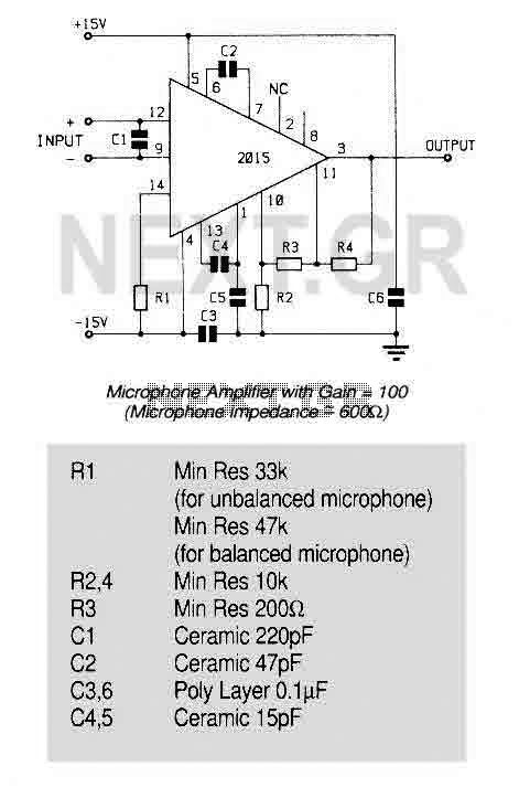
An ultra low noise audio preamplifier particularly suited to microphone preamplification including balanced microphones. The IC features wide bandwidth, low distortion only 0.007% at a gain of 100, and very low noise only 1.3nV/Hz for source impedance up to...
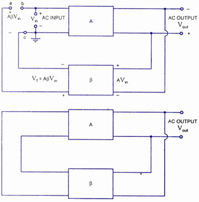
A feedback amplifier with a closed-loop gain, Af, greater than unity can be achieved through the use of positive feedback. This condition also fulfills the phase requirement, leading to the operation of an oscillator circuit. An oscillator circuit generates...
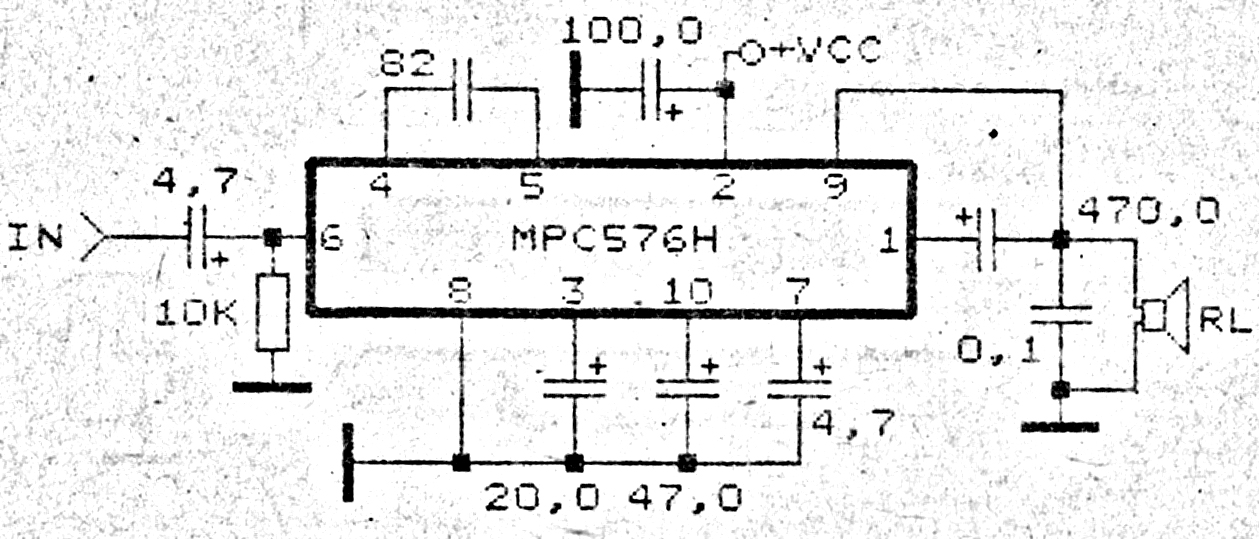
This amplifier circuit exhibits good sound quality. Although it does not provide high output power, it is capable of producing both soft and loud sounds reliably. The circuit utilizes a single IC, the MPC576H, along with several supporting components....
The following circuit diagram illustrates a simplified application circuit for the TDA8932B/33(B) device when it is powered by an asymmetrical supply (single supply). The TDA8932B/33(B) is a class-D audio amplifier integrated circuit designed for efficient audio amplification in various applications....
A basic detector radio set that utilizes a vacuum tube instead of a crystal detector. This radio requires minimal components, and due to its inherent simplicity, it is easy to construct. Despite its simplicity, this receiver performs well when...
The LM317 integrated circuit (IC) is commonly recognized as an adjustable voltage regulator. However, it also has the capability to function as an audio amplifier, specifically in Class A configurations. The LM317 can be utilized in audio amplification applications due...