
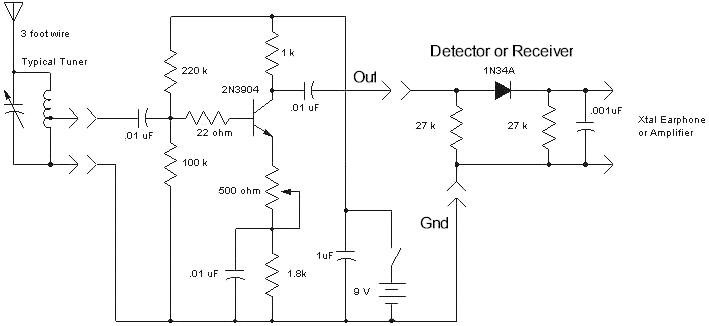
cr vacuum tube detector radio

The antenna coil L1 is 75 turns preferably with 10x0. 05 MM Litz wire, with taps at 15, 30 and 45 turns. These taps marked 2 and 3 on the schematic diagram, and they are useful for improved impedance matching. Coil inductance need to be around 200 uH with a 500-pF C1 capacitor Litz wire is a specially insulated multi-strand RF magnet wire; it has 10 strands, each 0.
05-millimeter diameter. The more conductors a Litz wire has the better. With smaller wire size, it gets progressively harder to remove the enamel from all the tiny strands for soldering. There are several commercial preparations available for just such purpose, they works well if not exactly fast.
Litz wire with low temperature insulation can be tinned directly, as the enamel melts off during soldering. Since multi-strand wire increases the wire`s surface area, it helps to reduce the coils impedance and to overcome the extra increase caused by the skin effects which forces RF (Radio Frequency) currents to flow mostly on the conductor`s surface.
More than one wire together may be used for the coil making with similar benefits. Any additional single conductor cuts the coil resistance proportionately and the skin effect will diminish too. Picture 2 shows a good quality, ceramic insulated, sturdy, air dielectric rotary capacitor. It is used for C1, and its value is 500 pF (pico Farad) when closed. D1 is a miniature vacuum tube, used as a signal detector. Although any vacuum tube would work in this circuit, the preferred one for this place is one of the low filament power electron tubes like the 1T4 that has a filament voltage of 1.
4 V and it uses only 50 milli-amperes [mA] for its operation. When using a tube that is not a diode, connect all the grids and other extra electrodes to the anode. The 1T4 is a pentode; it has three grids so tie them all together with the anode. The tube requires only power for its heater, and not much of it, so a standard single AA cell will work for a long time.
When the set is not in use disconnect the battery with the SW1 switch. The vacuum tube can be used to verify that the set works correctly then it can be replaced by a crystal detector. With a set of piezoelectric headphones, this radio provides near hi-fi (High Fidelity) sound as much as the AM bandwidth permits such quality reception.
As these types of headphones provide only capacitive loading, the 200 Kohm R1 resistor is required, and the 1 nF (nano Farad) capacitor is unused. Carefully done solder connections with rosin core solder, made for electronic soldering, are helpful.
Start up of the completed radio should be easy. Tune in a station, then select the taps on L1 that give the strongest signal. The way to select the tap is by listening to a station and to experiment with different tap points. If a very strong, high-powered local station is in the area, a wave trap circuit may be required. 🔗 External reference
Related Circuits
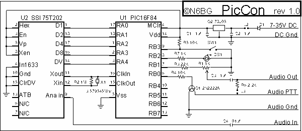
PicCon is a PIC microcontroller based radio controller designed for hidden transmitter hunting. When combined with a radio transmitter, it will produce tone sequences and Morse code messages at user-programmed times. It is completely field programmable via DTMF tones,...

An FM radio generates an interference signal that can be detected on another FM radio tuned 10.7 MHz higher than the original. A 50 kΩ potentiometer is used to adjust the modulation level to its maximum without introducing distortion....
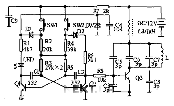
The circuit diagram illustrates a dual radio remote control switch system. The transmitter section features Q3, which generates a high-frequency carrier signal, while Q1 and Q2 form the oscillator circuit. Pressing switch SW1 results in an oscillation frequency of...
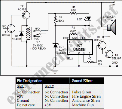
This circuit utilizes a complementary pair consisting of an NPN metallic transistor T1 (BC109) and a PNP germanium transistor T2 (AC188) to detect heat in the environment, such as that produced by a fire, and activate a siren. The...
The circuit presented is a straightforward yet efficient amplifier that can provide notable performance enhancements. This amplifier can demonstrate negative resistance at lower settings of the 500-ohm potentiometer, resulting in increased gain or even oscillation. Consequently, the circuit can...
The sensors consist of a thin strip of piezoelectric material with a rivet at one end acting as a weight. When vibration occurs, the weight moves, stressing the piezo material, which generates a spike in voltage that can reach...