
zero voltage switching
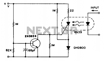
The SCR coupler circuit is designed to enhance the sensitivity of input signal detection, making it particularly advantageous in applications where low-cost components are preferred without sacrificing performance. The 4N39 (H11C3) optocoupler is a notable choice due to its cost-effectiveness and ability to operate efficiently with drive currents greater than 7 mA.
In this configuration, the optocoupler serves as an interface between the input signal and the output load, providing electrical isolation while allowing signal transfer. The circuit typically includes a phototransistor that responds to light emitted from an internal LED, which is activated by the input signal. The sensitivity of the circuit can be adjusted through the choice of resistors and capacitors in the input stage, allowing for optimal performance based on the specific application requirements.
The use of the 4N39 (H11C3) in this circuit is particularly beneficial in environments where cost constraints are a factor. The ability to work with higher drive currents ensures reliable operation in various conditions, making the SCR coupler circuit a versatile solution for signal processing needs. Overall, this design achieves a balance between performance and economy, suitable for a wide range of electronic applications.The SCR coupler circuit provides higher sensitivity to input signals as illustrated. This allows the lower cost 4N39 (H11C3) to be used with the > 7 mA drive currents supplied by the input circuit. 🔗 External reference
Related Circuits
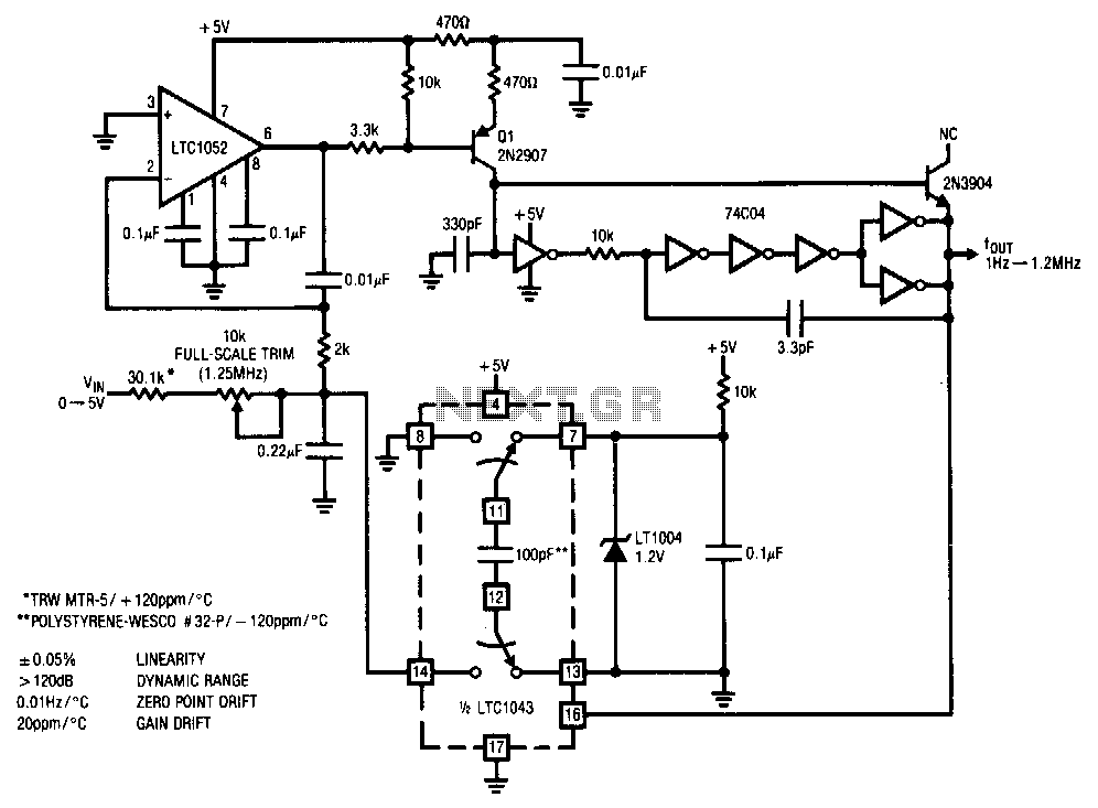
This stabilized voltage-to-frequency converter operates within a range of 1 Hz to 1.25 MHz, featuring a linearity of 0.05% and a typical temperature coefficient of 20 ppm/°C. The circuit is powered by a single 5-V supply. It employs a...
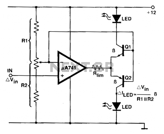
An operational amplifier (op amp) is utilized as a comparator and as a current sink for an LED. The output voltage of the amplifier varies by approximately 1.4 V based on the direction of the current. At any given...
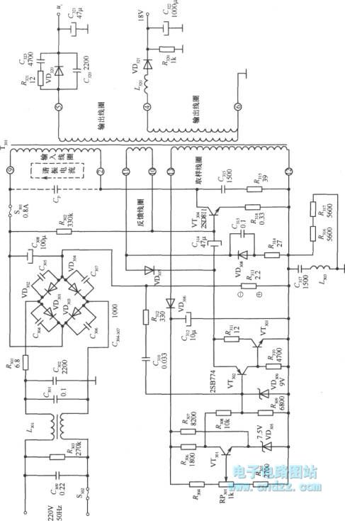
A high voltage switching stabilized voltage supply circuit is illustrated in the diagram. This is the switching power supply for an 80P type color television. It utilizes auto-excitation and a PWM circuit. The output is isolated from the power...
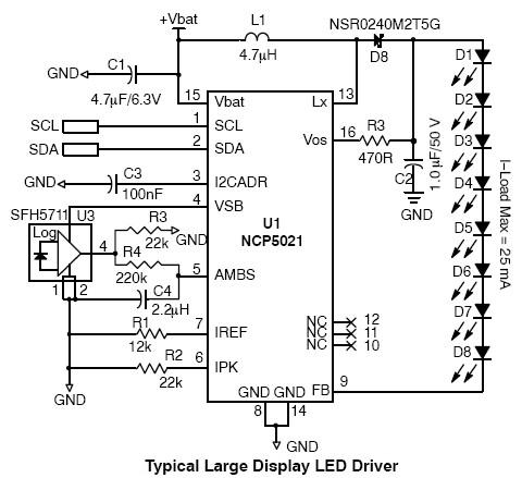
This high-voltage white LED driver electronic circuit schematic utilizes the NCP5021 integrated circuit from On Semiconductor. The NCP5021 is designed with an ambient light sensing feature and can drive up to eight LEDs in series for portable backlight applications....
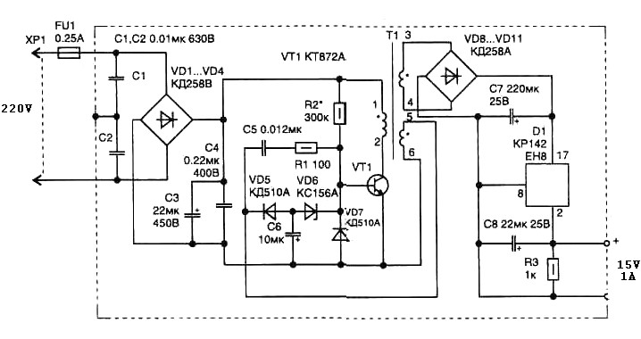
A 15 Watt switching power supply schematic diagram features a pulse transformer T1 constructed on a ferrite core M2500NMS-2 or M2000NM9, with a Sh5h5 size (cross-section of the magnetic coils at the location of 5G—5 mm with a gap...

A 12V constant voltage charger is depicted. The power supply circuit shares the same basic design. The resistor R1, valued at 0.2 ohms, serves a limiting function, effectively increasing the internal resistance of the charger, which in turn reduces...
Warning: include(partials/cookie-banner.php): Failed to open stream: Permission denied in /var/www/html/nextgr/view-circuit.php on line 713
Warning: include(): Failed opening 'partials/cookie-banner.php' for inclusion (include_path='.:/usr/share/php') in /var/www/html/nextgr/view-circuit.php on line 713