
Series DC power supply

The power supply circuit described functions as a versatile voltage regulator with a defined output. The transformer (T) is essential for stepping down the mains voltage from 220V AC to a lower voltage suitable for the subsequent rectification stage. The bridge rectifier, formed by diodes VD1 to VD4, converts the AC voltage to pulsating DC. The capacitor (C1) serves as a filter to smooth out the pulsations, leading to a more stable DC voltage.
The adjustment tube (VT2) plays a crucial role in regulating the output voltage. The output voltage (Uo) is set to 6V, but can be adjusted by varying the resistance of the sampling resistor (RP). This provides flexibility in the output voltage, allowing it to cater to different load requirements. The circuit is designed to handle a maximum output current of 200mA, making it suitable for various electronic applications.
The regulation mechanism relies on feedback control. When the output voltage deviates from the desired level, the resistor divider samples the output voltage and compares it against a stable reference voltage. The resulting error signal is amplified and used to adjust the base of the regulator, which in turn modifies the voltage drop across the adjustment tube (VT2). This feedback loop ensures that the output voltage remains stable despite variations in load or input voltage.
Stability in the output voltage is paramount, and it is influenced by the choice of the reference voltage and the amplification factor in the circuit. A stable reference voltage is critical; if it fluctuates, it can lead to variations in the output voltage, compromising the overall stability of the power supply. Silicon-based voltage regulators are often utilized due to their reliability and stable performance. Proper selection of current limiting resistors is also essential to maintain the minimum current required for the regulator to function correctly, which is necessary for achieving stable output voltages under varying conditions.
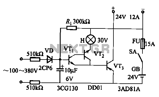
In summary, this power supply circuit is an effective solution for providing a stable and adjustable DC output voltage, suitable for powering various electronic devices while incorporating necessary protection and stability features.As can be seen, a power supply is usually the transformer, rectifier filter, adjust the yuan pieces, more zoom, six partial reference power supply and sampling, etc., there are some power supply overload or short circuit protection device. Circuit from 220V step-down transformer T to 10V, VD1 ~ VD4 bridge rectifier into a pulsating the AC 10V DC, through the capacitor c1 filter, and then by the regulation, amplification, sampling aspects, the adjustment tube VT2, the output DC Uo to 6V. Adjust the sampling resistor RP large small, you can change the output voltage U. 6V changes within the circuit output current Io is 200mA. It regulators working process is: when the output voltage changes, through a resistor divider to sample, after comparison with the reference power, amplification will amplify the error signal, to the base of the pole to adjust their regulator pressure drop in order to achieve a stable output voltage.
Generally speaking, an enlarged part of the greater magnification, the higher the degree of stability. Let Control 12 - Stability turns 21a as shown in a block diagram of each power supply as follows: (1) the reference voltage of a reference voltage should be higher DC voltage stability, otherwise, since the reference voltage is changed, even if the U, not variable t It will cause the output voltage changes, affecting the stability of the output voltage.
Currently. Often using a silicon reference voltage regulator vs Phoenix and achieved, as shown in Figure 12-21b, the key is to choose the regulator circuit current limiting resistor, the resistance should be guaranteed when the input voltage [ minimum flow through the regulator Parker tube current nor less than the minimum current to maintain stable voltages
Related Circuits
This is a high-quality stabilized power supply circuit diagram. The output voltage can be adjusted from 0 volts to 30 volts DC, and the current output value can be adjusted from 0.002 A to 3 A. The circuit begins...
An AC-DC power supply without a power switching circuit is typically employed in lighting load circuits. When the power grid is restored, the standby power supply automatically switches on. The automatic switching circuit utilizes a transistor, as illustrated. The...
The circuit diagram presented is for a compact mini audio power amplifier that operates with a DC supply voltage ranging from 4.5 volts to a maximum of 18 volts. This amplifier utilizes the TDA1015 integrated circuit, produced by NXP...
.jpg)
The HID ballast circuit consists of a buck stage for regulating lamp current and power, a full-bridge output stage that generates a low-frequency (200Hz) AC square-wave voltage and current to drive the lamp, and an ignition circuit that produces...
The circuit comprises two sections: charger power supply and LED driver. The charger power supply section is built around a 3-terminal adjustable regulator (IC1) LM317, while the LED driver section is built around transistor BD140 (T2). In the charger...
This circuit of power supply, are very simple in the manufacture, the finding of his materials, is very easy and cost, small. The output voltage is stabilised and is regulated in the region from 0V until + 15V dc,...