
0-15V 1A Variable power supply

This power supply circuit is designed to provide a stabilized output voltage ranging from 0V to +15V DC, with a maximum output current of 1A. The primary components include a transformer, a linear voltage regulator, capacitors for filtering, and a power transistor for current amplification.
The transformer (T1) is a standard 220V AC to 18V AC transformer rated at 1.5A. This transformer steps down the mains voltage to a lower AC voltage suitable for rectification. The output from the transformer is then rectified using a bridge rectifier configuration, which consists of four 1N4007 diodes (GR1). This configuration converts the AC voltage to pulsating DC voltage.
The pulsating DC output is smoothed using a large electrolytic capacitor (C1, 2200uF, 35V), which reduces the ripple voltage and provides a more stable DC voltage. Additional capacitors (C2, C3, C4, and C5) are included in the circuit to further filter the output and stabilize the voltage. C2 (100uF, 35V) is used for additional smoothing, while C3 (10uF, 25V) and C4 (220uF, 25V) help with transient response and stability. C5 (100nF, 100V) serves as a high-frequency bypass capacitor to filter out high-frequency noise.
The output voltage is regulated using a linear potentiometer (R2, 330 ohm), allowing for adjustable voltage output. The power transistor (Q1, 2N3055) is a classic choice for linear regulation, capable of handling significant current loads. It is crucial to mount the transistor on a heatsink to dissipate heat generated during operation, especially when delivering maximum current.
R1 (56 ohm, 2W) is used as a current limiting resistor to protect the circuit during startup and provide stability. A zener diode (D1, 18V, 1.5W) is incorporated to provide over-voltage protection and ensure that the output voltage does not exceed the desired level.
This circuit is suitable for various applications requiring a reliable and adjustable power supply, making it an excellent choice for hobbyists and professionals alike. The simplicity of the design, combined with the availability of components, contributes to its effectiveness and cost efficiency.This circuit of power supply, are very simple in the manufacture, the finding of his materials , is very easy and cost, small. The output voltage is stabilised and is regulated in the region from 0V until + 15V dc, with biggest provided current 1 A.
The regulation becomes with the R2. The Q1 of is classic power transistor and it needs it is placed in heatsink, one and heating when it works continuously in the region of biggest current. The type of transformer is standard in the market. R1= 56ohm 2W Q1= 2N3055 R2= 330ohm Lin. pot. T1=220V@18V 1.5A C1= 2200uF 35V C2= 100uF 35V D1= 18V 1.5W zener C3= 10uF 25V C4= 220uF 25V C5= 100nF 100V GR1= 4 X 1N4007 🔗 External reference
Related Circuits
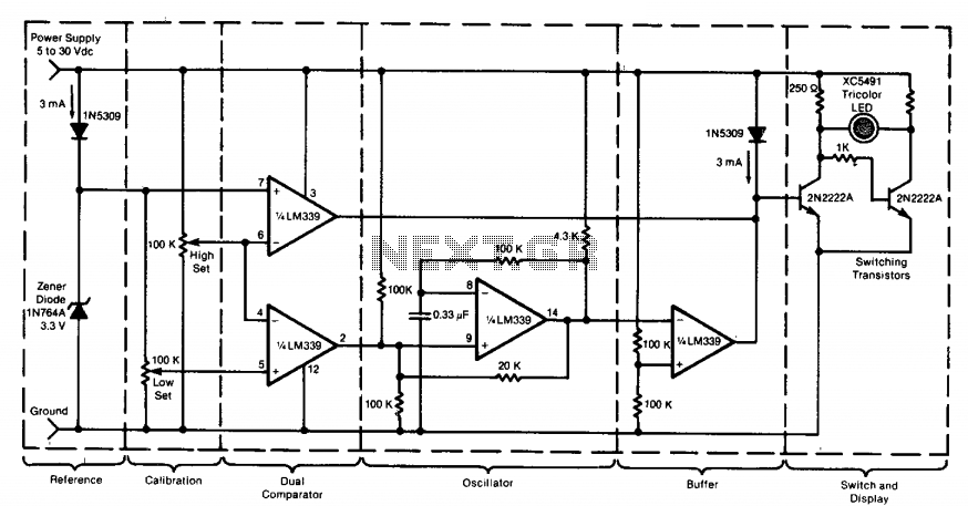
This circuit utilizes a tricolor LED display to signify acceptable and unacceptable output voltages. One LED indicates the upper voltage limit, while another indicates the lower voltage limit. When the monitored voltage exceeds the maximum set point, the LED...
The primary issue with the design of a stereo amplifier that includes a total bass driver is that the signals from the left and right channels eventually become combined. This summation process minimizes the separation between channels, compromising the...
The circuit diagram illustrates a voltage regulator designed from discrete components to meet specific voltage requirements. It provides two sets of component values for output voltages of 6.3 V (upper) and 12.6 V (lower). The components used include BC547...
This power supply circuit operates using 120 volts from household mains and should only be undertaken by individuals with the appropriate knowledge and skills to safely construct such a project. Failure to do so may result in personal injury...
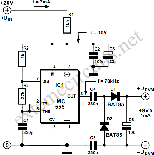
Most commercial digital voltmeter (DVM) modules with an LCD readout are powered by 9 volts and utilize an ICL7106 or similar analog-to-digital (A-D) converter chip. These modules are commonly employed in laboratory power supplies and other test and measurement...
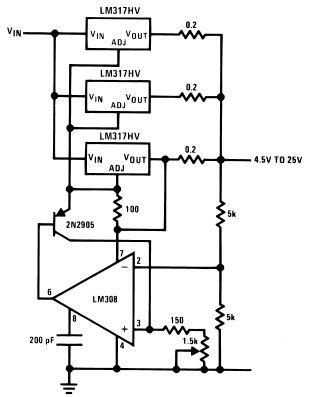
The LM317HV adjustable regulator is capable of supplying more than 1.5A across an output voltage range of 1.2V to 57V. The design of this high-current power supply is straightforward, as the LM317HV requires only a few external resistors to...