
555 audio oscillator circuit diagram of a radio-frequency drive

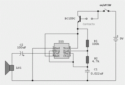
The circuit utilizes a 555 timer configured in astable mode to generate audio frequencies. The resistors R1 and RP1, along with capacitor C1, set the timing intervals that define the output frequency. The frequency of oscillation can be fine-tuned by adjusting the variable resistor RP1, allowing for a broad range of audio outputs suitable for various applications, such as tone generation or sound signaling.
The reset functionality of the 555 timer is crucial for controlling the oscillator's operation. When pin 4 receives a low signal, the timer is reset, halting any oscillation. This feature is particularly useful in scenarios where the circuit must remain inactive in the absence of an RF signal. The presence of an RF signal is detected by diode D1, which rectifies the incoming signal and applies a voltage to pin 4. If this voltage exceeds the threshold of 1V, it enables the oscillator, producing a continuous audio tone through the speaker.
Overall, this circuit exemplifies a simple yet effective method for generating audio signals based on external RF input, leveraging the versatile capabilities of the 555 timer IC. The design can be employed in various applications, including alarms, sound effects, and communication devices where audio signaling is required.As illustrated, 555 and R1, RP1, C1 and other components controlled audio oscillator, f frequency of 1.44/(R1 + 2RP1) C1, illustrated parameters between 600Hz ~ 20kHz, can be s elected by adjusting the RP1. The oscillator or not, depending on the reset terminal 4 foot level. When no RF signal, 4 feet was low, 555 state to stop vibration; when a designated radio frequency signal, the detector diode detector D1, the video signal is applied to pin 4, when the signal level is higher than 1V, the start-up, the speaker will be issued tone given audio signal
Related Circuits
This circuit is a conventional Pierce type oscillator that utilizes a JFET. It employs fundamental mode crystals and demonstrates good performance and reliability when a low noise JFET is used. The feedback is regulated by the capacitance C1, which...
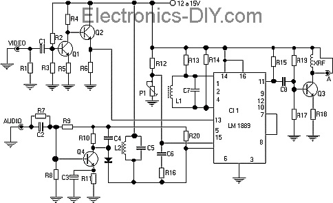
This TV transmitter transmits audio and video signals from camcorders, DVD players, VHS players, satellite systems, video games, etc., broadcasting them on a channel free from the VHF strip. These signals can be radiated using a common antenna and...
Probes or contacts may utilize a non-reactive metal. Gold or silver plated contacts from an old relay may be used; however, a cost-effective alternative is to wire alternate copper strips from a piece of veroboard. These will eventually oxidize,...

This is a circuit design for a doorbell that produces a sound resembling that of a bird. The circuit is controlled by an NPN transistor. The operation begins when P1 is set to an experimental value, starting with approximately...
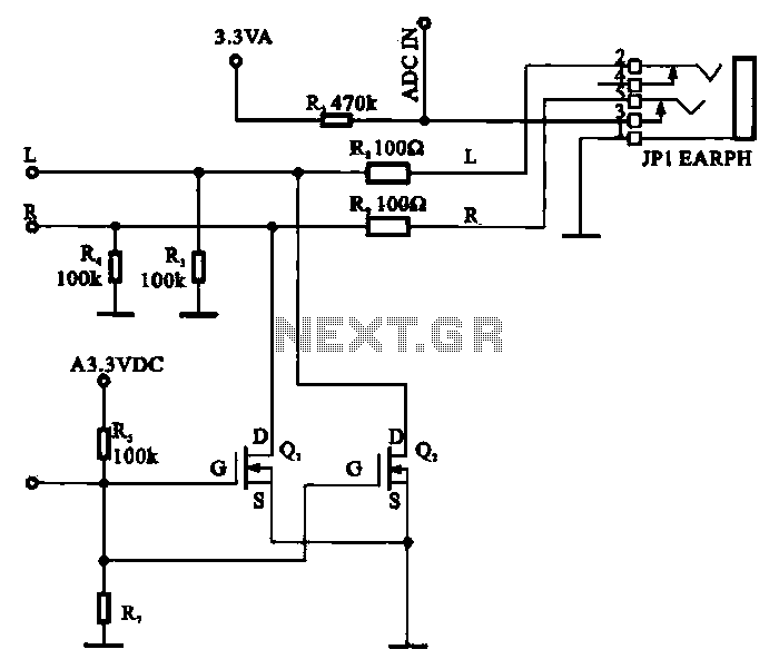
A field-effect transistor (FET) is utilized in a headphone circuit designed to function as a silencer tube. The circuit integrates L from the digital signal processing unit and R from the audio signal into the headphone jack's mute control...
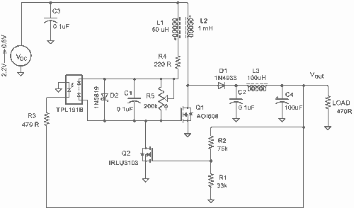
It employs a low threshold MOSFET and two coupled coils to function as a joule thief. An additional MOSFET is utilized for regulation. The circuit operates as a joule thief, which is a type of DC-DC converter designed to extract...