
555 multi-temperature test circuit configuration

The multi-channel temperature measurement circuit utilizes a 555 timer configured in a monostable mode to create time delays for sequential temperature readings. The operation begins with the pressing of a button, which triggers the 555 timer (IC1) to generate a high output signal. This signal energizes relay J1, activating the selected thermocouple channel and illuminating LED1 as an indicator of the active measurement.
The charging process of capacitor C1 through resistor R1 is critical in establishing the timing intervals. The time delay (td) for each measurement cycle is calculated based on the formula td = 1.1R1C1, allowing for precise control over the duration of each channel's activation. The circuit's design ensures that as the voltage across C1 reaches 2/3 of the supply voltage (VDD), the 555 timer resets, generating a low output signal. This low signal is coupled through a 0.01 µF capacitor to trigger IC2, which activates the next thermocouple in the sequence.
In scenarios where switch K1 is engaged, the circuit can continuously cycle through the thermocouples, providing real-time temperature measurements across multiple channels. The design incorporates an initial flickering of LEDs during power-up, which can be mitigated by implementing an R-C network. This network stabilizes the reset state of the 555 timer, preventing erratic behavior and ensuring a smooth transition into the measurement phase.
Overall, this multi-channel temperature measurement circuit is an effective solution for applications requiring simultaneous temperature monitoring across various points, with built-in visual indicators for operational status and enhanced accuracy through careful timing control.As shown in Fig multi-channel temperature measurement circuit. The test circuit consists of a core consisting of 555 one-shot delay circuit. When the button i s pressed AN, IC1 (555) due to the occurrence of low feet set, high pin output relay J1 pull, the corresponding thermocouple channel is turned on. Meanwhile, LED LED1 lights. By R1 and capacitor C1 is charged, when the charge voltage on C1 to make foot potential reaches 2/3VDD, the 555 reset occurs, low back pin output by 0.01 mu F after capacitive coupling pin was low so IC2, IC2 occurs is set.
Output level corresponding turns on the second thermocouple, repeat the process, so in turn trigger, multi-channel temperature testing. If the circuit closes the switch K1, the cycle can be detected, and each stage of the measurement time (delay time) is td 1.1R1C1, icon parameter corresponding to a delay of about one second.
Taking measurements at the same time, LED lights, for detection indication. On the circuit diagram (a), when the power-up may occur a few light-emitting diode LED flicker at the same time, therefore, can be used as shown in (b), improved circuit. After accessing R, C network, when turned on, since the C voltage can not change suddenly, so that 555 (Ic) reset terminal ( feet) in forced reset state, pin output low, the capacitor C is charged with the conduct, feet potential gradually rises when foot potential rise to the high level, Ic at all levels in the timed waiting state, thereby improving the accuracy of the test circuit.
This circuit is used when the multi-channel temperature testing, switch the thermocouple corresponding channel.
Related Circuits
PWM waveforms are frequently employed to regulate the speed of DC motors. The mark/space ratio of the digital waveform can be established either by utilizing an adjustable analog voltage level (as seen in a NE555-based PWM generator) or through...
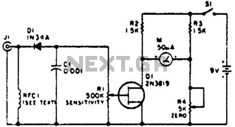
This circuit employs a FET as a DC amplifier within a bridge configuration. Resistor R4 is adjusted for meter nulling with switch J1 short-circuited. Any surplus 50-mA meter can be utilized in this circuit. RFC1 represents a suitable RF...

This circuit represents a negative resistance configuration. All previous circuits utilize RC time constants to achieve resonance. LC combinations can also be employed, providing good frequency stability, high Q factor, and rapid startup. In this circuit, a signal input...
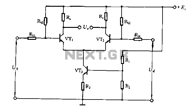
The differential amplifier circuit features a constant current source. The differential amplifier is a fundamental building block in analog electronics, utilized for amplifying the difference between two input voltages while rejecting any signals that are common to both inputs. Central...
Configured with capacitive coupling by inserting a small capacitor between the phototransistor and the bipolar transistor, this relay circuit will respond only to rapid changes. This relay circuit utilizes capacitive coupling to enhance its responsiveness to fast signal changes. The...
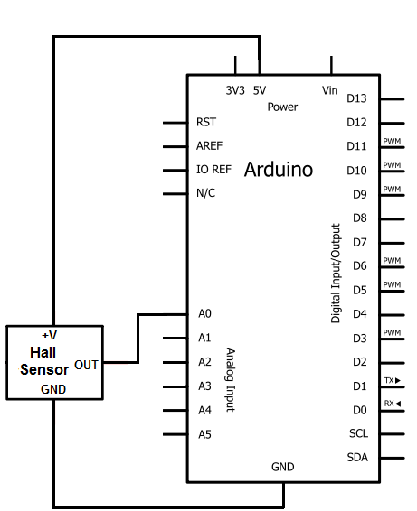
The Hall effect sensor utilized in this circuit is the A1302 Hall effect sensor manufactured by Allegro. This integrated circuit (IC) is capable of detecting magnetic fields. It will be connected to an Arduino, allowing the Arduino to read...