
Differential amplifier circuit has a constant current source

The differential amplifier is a fundamental building block in analog electronics, utilized for amplifying the difference between two input voltages while rejecting any signals that are common to both inputs. Central to its operation is the constant current source, which provides a stable biasing current to the transistors in the circuit. This ensures that the amplifier maintains consistent performance across varying conditions.
In a typical configuration, the differential amplifier consists of two input transistors, often bipolar junction transistors (BJTs) or field-effect transistors (FETs), arranged in a complementary manner. The constant current source is connected to the emitters (in the case of BJTs) or sources (for FETs) of the input transistors, allowing for precise control over the quiescent operating point of the amplifier.
The output of the differential amplifier can be taken from the collectors (for BJTs) or drains (for FETs) of the input transistors. The differential gain of the amplifier is primarily determined by the load resistors connected to these outputs and the transconductance of the input devices. To enhance the common-mode rejection ratio (CMRR), additional stages or feedback mechanisms may be employed, improving the overall performance of the amplifier in real-world applications.
In summary, the differential amplifier circuit with a constant current source is designed to provide high accuracy and stability in amplifying differential signals, making it suitable for applications such as instrumentation, signal conditioning, and audio processing.Differential amplifier circuit has a constant current source road
Related Circuits
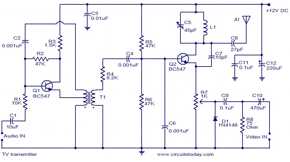
A simple two-transistor TV transmitter circuit that operates from 12V. It is compatible with PAL B and PAL G systems. The described circuit utilizes two transistors to create a basic television transmission system capable of operating on a 12V power...
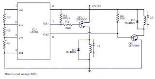
The values of the LM56 thermostat project circuit diagram for resistors R1, R2, and R3 at the travel points VT1 and VT2 can be determined using the following equations. This electronic circuit thermostat with the IC LM56 serves as...
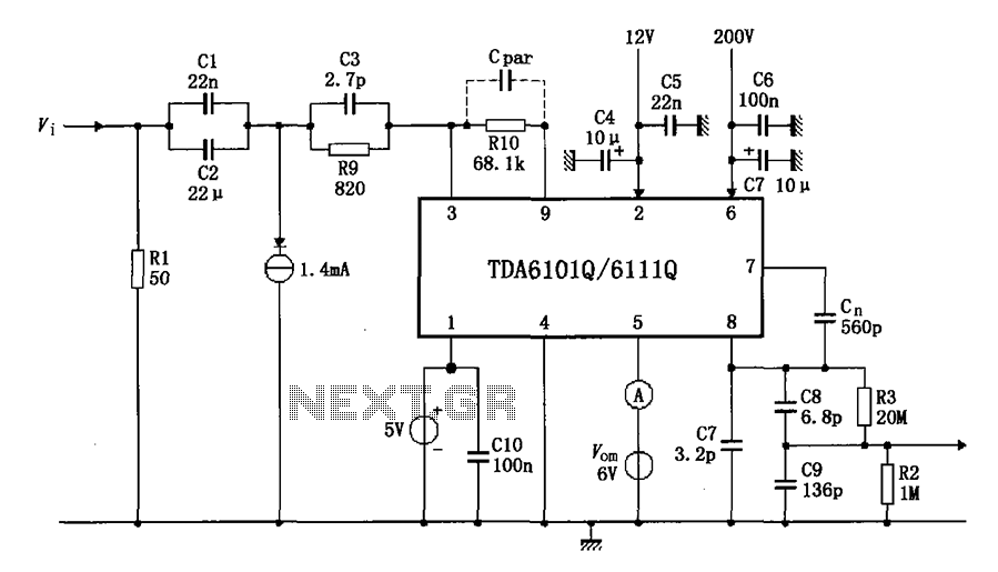
The test circuit features a feedback factor of 1/83 utilizing the DA6101Q/6111Q. The input signal is fed through a network comprising resistors R1 and R9, and capacitors C1, C2, and C3, entering the TDA6101Q, which includes three pins for...
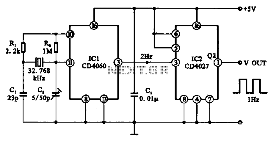
A 1Hz clock signal generator circuit is presented, which demonstrates a sophisticated clock signal generating mechanism. This circuit can be utilized for digital clocks and timing applications. It comprises a binary counter (CD4060), a JK flip-flop (CD4027), and a...
Six timing positions suited to different skin types; timing affected by sunlight intensity. This timer was designed for individuals seeking to achieve a tan. The electronic timer circuit described is intended for use in tanning applications, specifically designed to cater...
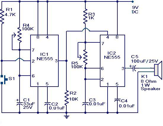
The primary component of this circuit is a doorbell utilizing two NE555 timer ICs. When the switch S1 is momentarily pressed, the speaker produces a bell sound, which is determined by the time period of the monostable multivibrator configured...