
555 monostable circuit is used as a table or capacitance resistance meter schematic

The circuit operates by initially charging the capacitor Cx through the resistors R1 to R3, which set the timing characteristics of the 555 timer in monostable mode. The output pulse width, td, is determined by the formula td = 1.1RCx, where R is the equivalent resistance seen by the capacitor during its charging phase. As the capacitor charges, the voltage across it rises until it reaches the threshold level of 2/3 Vdd, at which point the output of the 555 timer goes low, terminating the pulse. This duration of the pulse is directly related to the capacitance value, allowing for an indirect measurement of capacitance.
To utilize the circuit for resistance measurement, the measured resistance Rx can be connected in series with a fixed capacitor C. By adjusting the range change switch and recalibrating the meter, the circuit can accurately measure resistances. The output waveform can be visualized on an oscilloscope, displaying the pulse width corresponding to the capacitance or resistance being measured. The design is versatile, allowing for both capacitance and resistance measurements through minimal modifications, making it a valuable tool for electronics testing and diagnostics. As shown by 555 and the timing resistor R1 ~ R3 and measured capacitance Cx can be composed pointer capacitance meter, one-shot circuit capacitance measurement principle is the use Cx greater capacity, the greater the stability of the one-shot pulse temporarily that the voltage on Cx charge to the threshold level (2/3Vdd) the time required for longer. Due td 1.1RCx relationship, so when the input pulse triggers a fixed period, the output of the average amplitude of td (or Cx) is proportional to the relationship between the use of its amplitude of the ammeter to detect current flowing through the meter It reflects the size of the output pulse width td 555 size, which reflects the size of the capacity Cx.
If the circuit Cx exchanged for a fixed capacitance C, and the measured resistance Rx R will be placed in a position, through the range change switch and recalibration of the table, the table can be used as resistance measurements. Figure b its waveform.
Related Circuits
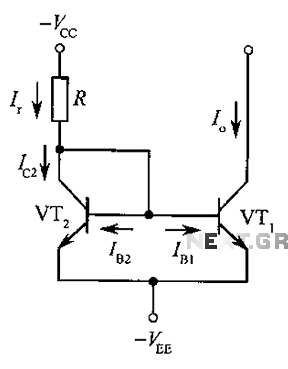
The circuit depicted is a mirror substantially constant current source circuit, in which transistors VT1 and VT2 are matched to each other. The figure illustrates that the current through Ir is equal to Ic2 plus the sum of base...
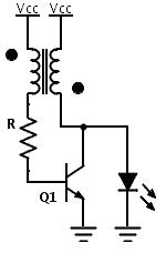
Previously, a boost circuit was tested that enables the powering of a 3 V LED using a discharged battery (approximately 1 V or lower). This circuit consists of a single transistor, one resistor, and a small transformer with a...

This circuit has a long history, originating from an idea by Rich Piotter and later refined by Wilf Rigter and Bruce Robinson. The final result does not include the necessary motor drivers, which are typically H-bridge based, but presents...
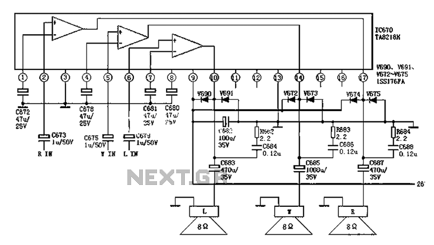
The audio circuit depicted in the figure is commonly utilized in color television systems. The pin functions and reference voltages for the TA8218AH are as follows: Pin 1: 1.9V - inverting input; Pin 2: 2.1V - R-channel audio signal...
The circuit for the localizer is based on a quad-band GSM/GPRS module interfaced with a microcontroller. After initializing the I/Os and UARTs, the microcontroller enters a loop waiting for events, such as the arrival of an SMS or the...
Today, it is no longer necessary to use discrete components for constructing oscillators. Many manufacturers now offer ready-made voltage-controlled oscillator (VCO) integrated circuits (ICs) that require only a few external components to determine the frequency. An example of such...