
TV audio circuit diagram TA8218AH

The TA8218AH is an integrated audio amplifier used primarily in color television sets, designed to enhance audio performance by providing both left and right channel outputs along with additional functionalities like bass signal processing and mute control. The pin configuration plays a crucial role in the overall operation of the circuit.
The inverting inputs on pins 1, 4, and 7 are essential for signal processing, allowing the amplifier to effectively manage audio signals from various sources. The R-channel and L-channel audio signal input terminals (pins 2 and 6) facilitate the input of audio from the television's audio source. The bass audio signal input on pin 5 is specifically tailored to enhance low-frequency sounds, contributing to an improved audio experience.
Ground connections are established through pins 3 and 13, ensuring a stable reference point for the circuit, which is necessary for proper operation and noise reduction. The power supply pin (pin 9) is critical for the amplifier's functionality, providing the necessary voltage to drive the circuit. The outputs for the left and right channels are found on pins 10 and 17, respectively, delivering the amplified audio signal to the speakers.
The mute functionality is accessible through pins 11 and 16, which can be employed to silence the audio output as needed. Additionally, the unused pins (12 and 15) may be reserved for future enhancements or specific applications, allowing flexibility in design. The filter pin (pin 8) plays a role in signal processing, ensuring that the output audio is clear and free from unwanted noise.
Overall, the TA8218AH audio circuit is a sophisticated solution for audio amplification in color televisions, with a well-defined pin layout that supports various audio processing capabilities. As shown in FIG audio circuit is commonly used in color television, TA8218AH pin functions and reference voltage: Pin 1: 1.9V-- inverting input Pin 2: 2.1V - R-channel audio si gnal input terminal Pin 3: 0V-- ground 4 feet: 1.9V-- inverting input 5 feet: 2.1V-- bass audio signal input terminal Pin 6: 2.1V - L-channel audio signal input Pin 7: 1.9V-- inverting input 8 feet: 8.9V-- filter 9-pin: 26V-- Power 10 feet: 13V - L-channel audio signal output 11 feet: 4.7V-- Mute 12 feet: 4.5V-- empty 13 feet: 0V-- ground 14 feet: 13V-- bass signal output 15 feet: 5.0V-- empty 16 feet: 4.6V-- Mute 17 feet: 13V - R-channel audio signal output
Related Circuits
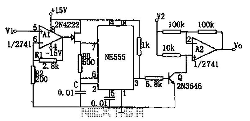
The circuit depicted in the figure consists of a voltage-frequency converter and an amplitude modulator. The input voltage V1, processed by operational amplifier A1, controls the FET 2N4222's internal resistance, which in turn alters the oscillation frequency of the...
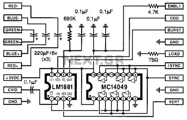
Using two LT1228 transconductance amplifiers in front of a current feedback amplifier creates a video fader. The ratio of the set currents into pin 5 determines the ratio of the inputs at the output. The proposed circuit utilizes two LT1228...
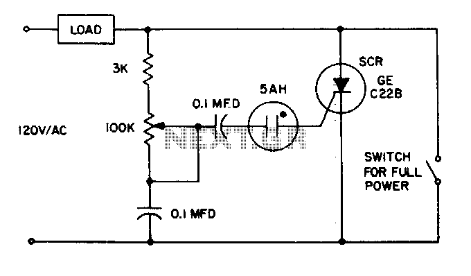
The 5AH will trigger when the voltage across the two 0 µF capacitors reaches the breakdown voltage of the lamp. Control can be obtained from full off to 95% of the half-wave RMS output voltage. Full power can be...
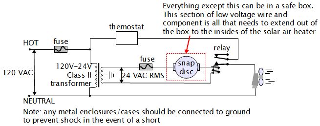
For various experiments, such as solar air heaters, an automatic fan activation and deactivation system is required. A straightforward solution is to use a bimetal snap disc thermal sensor. This sensor functions as a switch that closes when a...
GND and VCC are positioned perpendicularly to the other pins in the circuit diagrams, while the actual Z80 is a DIP with no pins in these locations. This arrangement complicates the readability of the circuit diagram, necessitating a mapping...
D1, D2, C1, and C2 double the AC input voltage, charging capacitor C3 through resistor R1 to approximately 320 volts. Resistor R1 isolates the voltage doubler from the discharge capacitor C3, ensuring that capacitors C1 and C2 do not...