
Battery consists Wll7 W217 W317 configuration application circuit

The W317 adjustable voltage regulator circuit serves as a versatile solution for battery charging applications, enabling precise control over the voltage and current supplied to the battery. The circuit is designed to ensure safe charging conditions by incorporating various current-limiting components that help prevent damage to both the battery and the charging circuitry.
In the first configuration, the constant pressure limiting charger circuit utilizes resistor Rs to manage the initial charge rate. This is crucial in preventing excessive current from flowing into the battery when it is in a low state of charge, which could otherwise lead to overheating or damage. The value of Rs should be selected based on the specifications of the battery being charged, taking into account its capacity and recommended charge current.
The second configuration introduces an additional layer of protection through the use of resistor R3. This resistor is strategically placed to limit the maximum charging current that can pass through the transistor, thereby protecting it from potential overload conditions. By carefully calculating the resistance value of R3, the maximum allowable current can be set, ensuring that the transistor operates within its safe limits throughout the charging process.
Overall, the W317 adjustable voltage regulator circuit exemplifies a well-thought-out design that not only provides adjustable voltage output but also incorporates essential safety features to enhance the reliability and efficiency of battery charging operations. Proper implementation of these components will result in a robust charging solution suitable for a variety of battery types. As shown by W317 is being integrated three-terminal adjustable voltage regulator circuit consisting of a battery charging applications. FIG. (A) given constant pressure limitin g charger circuit, wherein Rs is used to limit the charge current, to reduce the initial charge rate; Figure (b) is given still another limiting charging circuit, and wherein the resistor R3 used to limit the maximum charging current of the transistor.
Related Circuits
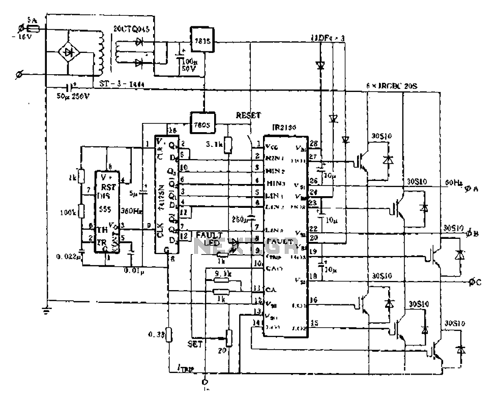
The application of the aforementioned advantages allows the IR2130 to be effectively utilized for DC cut crossing speed, DC servo systems, three-phase power inverters, and switching power supplies. Additionally, it is applicable in inverter power supplies, uninterruptible power supplies...
USB Battery Charger for Lithium Ion batteries using the LM3622 is a specialized charger circuit designed to operate with power sourced from a USB connection. The current consumption of the LM3622 is limited to 400mA by a resistor (R1),...
NE5532DR absolute maximum ratings: (1) Supply voltage: VCC+ 22 V; VCC-: -22 V; (2) Input voltage, either input VCC ±; (3) Input current: ±10 mA; (4) Duration of output short circuit: Unlimited; (5) Package thermal impedance, JA: D package...
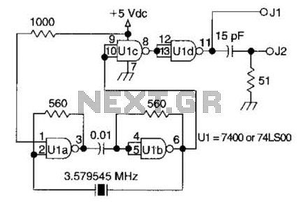
A circuit utilizing one 7400 TTL can operate with fundamental type crystals ranging from 1 to approximately 13 MHz. The output is rich in harmonics, making this oscillator suitable for calibration and testing applications. The circuit in question employs a...
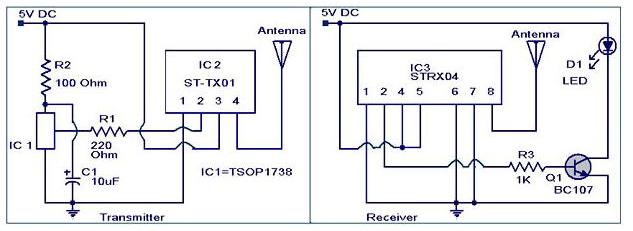
The IR to RF transmitter circuit described here can convert infrared (IR) signals from a remote control into radio frequency (RF) signals, allowing for long-distance transmission. This circuit effectively extends the range of an IR remote control and does...
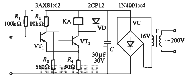
When the input is disconnected, the transistor VTi conducts, while VTz is in cutoff, causing relay KA to release. When the input is shorted, VTi is cut off, VTz conducts, and relay KA is activated. In this circuit configuration, the...