
IR to RF converter circuit

The circuit comprises several key components that work together to facilitate the conversion and transmission of signals. The TSOP 1738, an IR receiver module, captures the IR signals emitted by a remote control. It outputs a digital signal that corresponds to the received IR code. This output is fed into the ST-TX 01 ASK transmitter IC (IC2), which modulates the digital signal onto a carrier frequency suitable for RF transmission. The modulation process allows the signal to be effectively transmitted over greater distances compared to standard IR communication.
The antenna connected to the ST-TX 01 transmitter plays a crucial role in radiating the RF signals into the surrounding environment. The design ensures that the transmitter operates efficiently at a power output of 16 dBm, which is adequate for typical remote control applications, allowing for a significant range of operation.
On the receiving end, the ST-RX04 ASK receiver IC (IC3) captures the RF signals transmitted by the ST-TX 01. IC3 demodulates the received RF signal, extracting the original digital signal that represents the IR code. This demodulated signal is then sent to the output pin (pin 2), which drives the base of the transistor (Q1). The transistor acts as a switch, controlling the current flow to the IR LED (D1), which emits the infrared light corresponding to the original remote control signal.
This configuration allows for seamless communication between the remote control and the receiving device, effectively overcoming the limitations of traditional IR communication, such as the need for line of sight. The overall design is suitable for various applications, including remote control systems for TVs, audio equipment, and other consumer electronics, enhancing user convenience and operational range.The IR to RF transmitter circuit given here can convert the IR signals from your remote to RF signals to long distances. The circuit given here is a good one for extending the range of your IR remote. Also such systems does not need a line of sight since RF signals are used. The transmitter is based on a St-TX 01 ASK transmitter IC (IC2). The IR sig nals falling on IC 1 (TSOP 1738) will be converted to RF signals by IC2 and transmitted through antenna. The transmitter has a power output of 16dBm at 5V supply. The receiver is based on a ST-RX04 ASK receiver IC (IC3). The IC3 receives the transmitted code, decodes it to the original IR code and re transmits through IR LED (D1).
The transistor Q1 is used to drive the D1 from the output of the IC3(pin2). 🔗 External reference
Related Circuits

In this circuit, a TU31 shunt regulator is utilized to monitor the output voltage. The TU31 activates the LED of a 4N28 optocoupler, which delivers feedback to the MAX641 while ensuring isolation between the input voltage of +12 V...

A simple circuit that can generate an inverted square wave similar to the one used by the inventor on his function generator. To construct a circuit that produces an inverted square wave, a basic approach involves using a 555 timer...

This is a solar charger circuit designed to charge Lead Acid or Ni-Cd batteries using solar energy. The circuit captures solar energy to charge the batteries. The solar charger circuit typically consists of several key components, including a solar panel,...
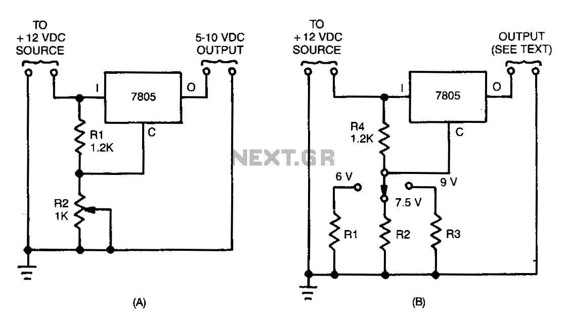
Many devices operate from a car's 12-V electrical system. Some require 12 V, while others need a lower voltage. An automobile battery's output can vary from 12 to 13.8 V under normal circumstances. The load requirements of the device...
The name of our game, LED Zeppelin, is a play on words. It comes not from the pop group of the same name but from Graf Von Zeppelin, a German who invented the first rigid air ship in 1900....

The BISS0001 is a high-performance integrated circuit designed for sensor signal processing. When combined with pyroelectric infrared sensors and a minimal number of external components, it forms a passive pyroelectric infrared switch. This device can automatically and quickly activate...