
Flash light emitting diode display circuit

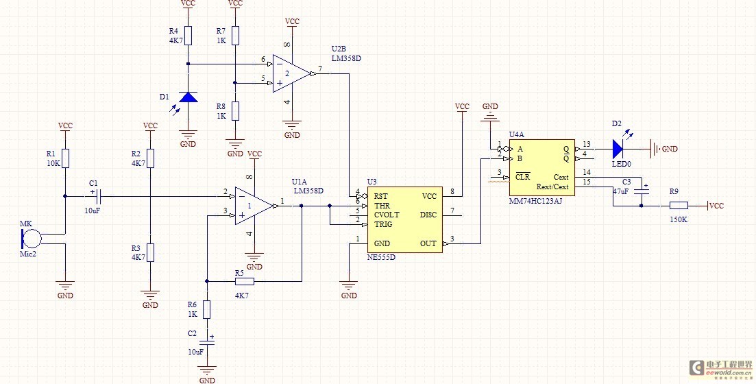
This circuit employs a multivibrator configuration, typically a 555 timer IC or a similar component, to generate a square wave output that drives one or more light-emitting diodes (LEDs). The multivibrator can be configured in astable mode, which allows it to continuously oscillate between high and low states, thereby producing a flashing effect.
In the proposed circuit, the 555 timer is connected with appropriate resistors and capacitors to set the desired frequency of the flashing LEDs. The output pin of the timer is connected to the anode of the LED, while the cathode is connected to ground through a current-limiting resistor. This resistor is crucial as it ensures that the current flowing through the LED does not exceed its maximum rating, thus preventing damage.
Additionally, the circuit can be enhanced by incorporating multiple LEDs in parallel or series to create various visual effects, such as simulating the blinking of eyes. The choice of LED colors can also be varied to achieve different aesthetic results.
Powering the circuit can be accomplished using batteries or a DC power supply, depending on the intended application. For toys, a compact battery solution is often preferred for portability.
In summary, this multivibrator-based LED display driver circuit provides an engaging visual effect suitable for toy applications, effectively simulating the blinking of eyes in animals or monsters. As shown by the multivibrator flashing light emitting diode display driver circuit can be used in toys in the eyes of animals or monsters double eyes flash.
Related Circuits

FIG M is a variable speed motor control for the opening and closing of a wicket gate. It features an electric governor. The system is activated by a power switch (SA) located on the front grid, and a toggle...
This 1 Hz and 2 Hz generator or oscillator is constructed using a 4060 IC as the oscillator and a 14-bit counter. To achieve a 1 Hz signal from the 4060, a 1/2 4013 flip-flop is utilized. This circuit...
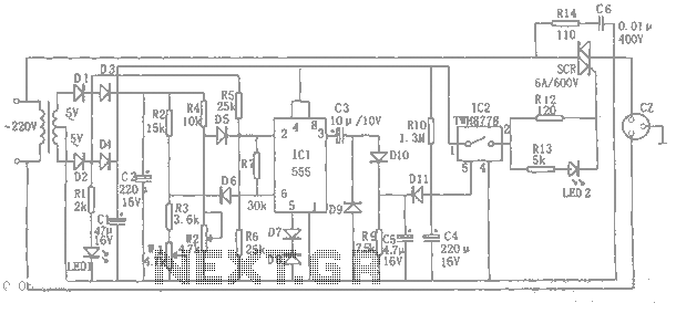
An automatic power protection circuit is presented. This protection includes a step-down rectifier circuit, an overvoltage and undervoltage detection circuit, and a delay switch control circuit. The step-down circuit is responsible for the entire rectifier circuit's DC voltage. The automatic...
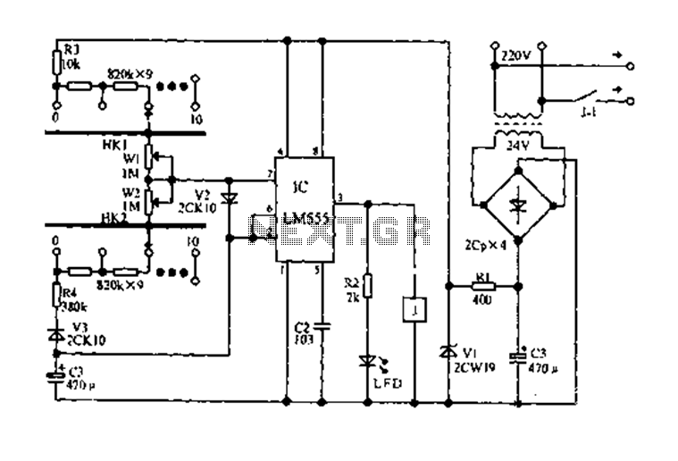
The circuit diagram for an electric start and stop timer is illustrated in the following cycle. It utilizes the LM555 integrated circuit configured as an adjustable duty cycle multivibrator. The circuit includes components C3, KH1, W1, KH2, and W2,...
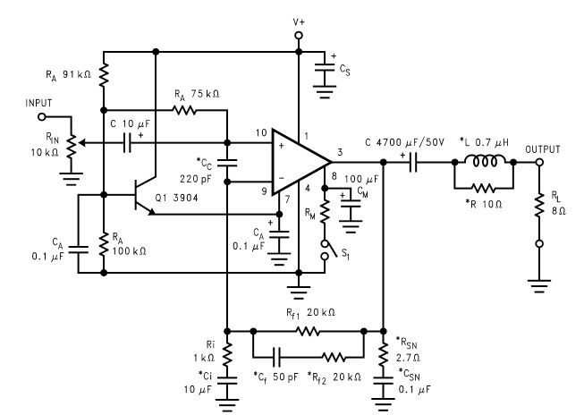
The LM2876 audio power amplifier circuit can be designed as a simple, high-efficiency power audio amplifier capable of delivering 40W of continuous average power to an 8-ohm load with a total harmonic distortion plus noise (THD+N) of 0.1% from...
The optically-controlled circuit plays a crucial role in urban street lighting and corridor illumination. By utilizing this circuit, lighting lamps can be automatically turned on and off based on ambient light levels, thereby reducing the need for manual control,...