
555 automatic power-protection circuit diagram

The automatic power protection circuit is designed to safeguard electronic devices from voltage fluctuations that could potentially cause damage. The step-down rectifier circuit serves as the initial stage, converting the input AC voltage to a lower DC voltage suitable for the subsequent components. This step-down operation is crucial in ensuring that the voltage levels remain within safe operating limits.
The overvoltage and undervoltage detection circuits are integrated to monitor the output voltage continuously. They employ voltage sensing mechanisms to detect any deviations from the predefined voltage thresholds. When an overvoltage condition is detected, the circuit activates protective measures, such as disconnecting the load or triggering an alarm, to prevent damage to the connected devices. Conversely, in the event of undervoltage, the circuit can initiate a shutdown procedure to safeguard the equipment from insufficient voltage levels that could lead to malfunction or damage.
The delay switch control circuit plays a vital role in managing the timing of the power restoration after a fault condition has been detected. This delay is essential to allow transient conditions to stabilize before reapplying power to the load. It prevents unnecessary cycling of the power, which could lead to further issues.
Overall, this automatic power protection circuit is an essential component in modern electronic systems, providing robust protection against voltage anomalies and ensuring the reliability and longevity of sensitive electronic devices.Shown automatic power-protection circuit. This protection consists of step-down rectifier circuit, overvoltage and undervoltage detection circuit, delay switch control circuit. Wherein the step-down circuit for the entire rectifier circuit DC voltage.
Related Circuits
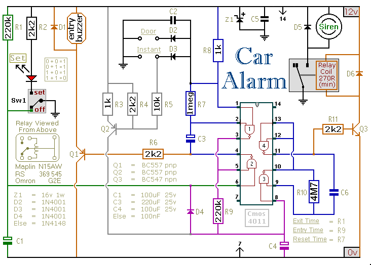
This car alarm circuit includes exit and entry delays, an instant alarm zone, an intermittent siren output, and automatic reset. By incorporating external relays, it is possible to immobilize the vehicle and activate the flashing lights. The car alarm circuit...
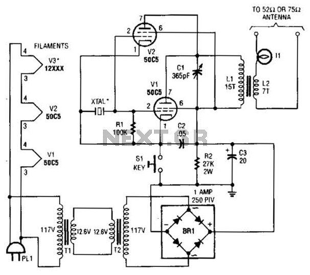
This low-power video transmitter is designed for remote control (R/C) applications, surveillance, or amateur radio purposes. It utilizes seven transistors within a crystal oscillator-multiplier RF power amplifier chain, along with a high-level video modulator. A supply voltage of 9...
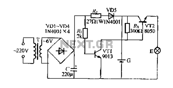
Figure 282 illustrates a simple emergency lamp circuit designed to activate during a power outage. The circuit utilizes a transformer (T) for voltage stepping, diodes (VD1 to VD4) for rectification, and a capacitor (C) for smoothing the output. During...

After the SCM execution, the Pl output port connects to the bidirectional input of 74LS245 driver chips. This driver operates during each phase of digital control, based on the information from the Pl port. The purpose is to convert...
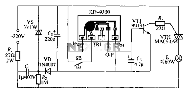
The circuit utilizes a KD-9300 music IC, which activates when the button switch (SB) is pressed, causing the electric lamp (E) to light up for approximately 20 seconds before automatically turning off. The setup includes a half-wave rectifier and...
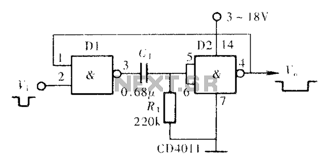
A CMOS NAND gate or NOR gate can form a monostable multivibrator, commonly referred to as a single-shot. This circuit is extensively used to delay pulse signals, allowing for signal stretching and shaping. The main principle involves utilizing the...