
PGA103 offset voltage correction circuit diagrams

The PGA103 offset voltage correction circuit is a critical component in precision analog applications, particularly in laser systems where accurate voltage levels are paramount. The circuit's design leverages the high-performance characteristics of the PGA103 and the OPA602 operational amplifier. The PGA103 is a programmable gain amplifier (PGA) that provides adjustable gain settings to accommodate various applications, while the OPA602 serves as a buffer to isolate the PGA from the subsequent circuitry, thereby enhancing overall system stability and performance.
In this configuration, the OPA602's role as a voltage follower is crucial. It provides a low output impedance, which is essential when interfacing with the PGA103. This low impedance ensures that the output of the correction circuit does not load the PGA103, preserving the integrity of the gain settings. The 50k potentiometer allows for fine-tuning of the offset voltage, enabling the user to achieve a zero-offset condition, which is vital for accurate signal processing.
The relationship between the output voltage Vo, the input voltage VIN, and the trim voltage VTRIM is defined by the equation Vo = VIN - VTRIM. This relationship highlights the importance of the trim voltage in calibrating the output to the desired level. The logic inputs A0 and A1, referenced to the ground, play a significant role in the digital control of the PGA103. The output voltage VTRIM must be carefully set to 0.1V to ensure that the logic threshold voltages are calibrated correctly, which is essential for the reliable operation of the system.
Overall, this circuit exemplifies the integration of analog and digital components to achieve high precision in voltage correction, making it suitable for applications that require stringent control over offset voltages and gain settings. As shown for the PGA103 offset voltage correction circuit. PGA103 laser correction, so the gain of the three kinds of typical offset voltage (relative to input) are lower than 200 V, and the gain of each different offset voltage. FIG OPA602 operational amplifier connected as a voltage follower as a buffer, the use of low voltage follower output impedance characteristics, in order to make the correction circuit and the low resistance of PGA103 pin is connected in order to maintain the accuracy of the amplifier gain. 50k potentiometer allows adjusting the offset voltage is zero, then the output voltage Vo G (VIN-VTRIM).
Because the logic inputs A0, A1 is referenced feet, so OPA602 output voltage VTRIM affect calibration logic threshold voltage, and therefore should be VTRIM 0.1V.
Related Circuits
To comprehend the interconnections between the following circuits, it is essential to first review the concept chapter. It is at the discretion of the user to select one or two of these circuits for personal development. The discussion begins...
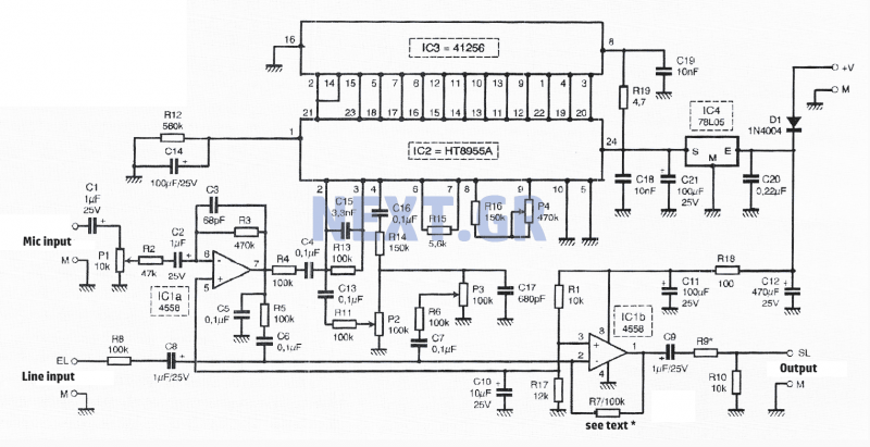
This fast circuit is compatible with any amplifier that has a line or high-level input (radio, CD) that allows mixing signals from a microphone with a chosen music source and adding adjustable sound effects to the voice. The circuit...

This circuit creates an impressive display of magnetism by suspending a small metal object in mid-air. Utilizing an electromagnet, a photo sensor, and a closed-loop control system, lightweight metal objects can be levitated just beneath the magnet, enclosed in...
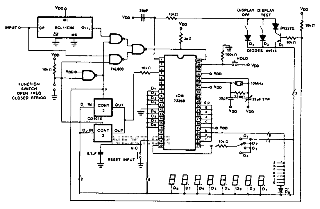
A CD4016 analog instrument is utilized as a multiplexed digital output, transferring the output function back to the input. The CD4016 operates as a digitally controlled analog transmission gate, eliminating the need for a digital output level shift. Alternatives...
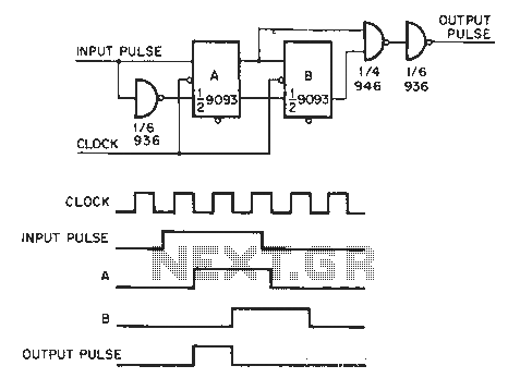
The circuit generates a clock that is synchronized with the pulse width of two clock pulses, producing a random pulse width that is five times the input pulse width of the clock pulse. In the flip-flop circuit, A and...
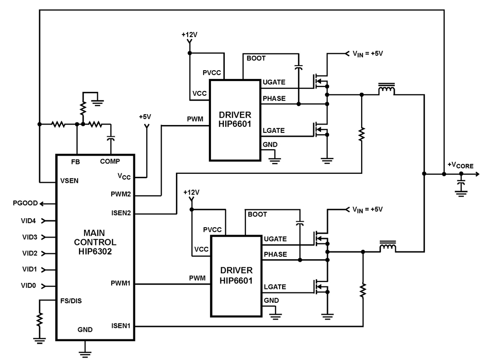
The HIP6302 Multiphase PWM control IC, along with its companion gate drivers (HIP6601, HIP6602, or HIP6603) and Intersil MOSFETs, delivers a precise voltage regulation system for advanced microprocessors. Multiphase power conversion represents a significant advancement over traditional single-phase converter...