
Circuit diagramms of the 144 SBB/RX - Receiver

The 6 MHz oscillator circuit is designed to achieve optimal frequency stability over extended periods. The use of multiple buffer stages serves to isolate the output frequency from variations in load conditions, ensuring consistent performance. This design consideration is critical in applications where precise frequency control is required, such as in communication systems or signal processing.
In the 36 MHz oscillator configuration, the presence of a shunt diode has been identified as a source of increased phase noise, which can adversely affect the oscillator's performance. Therefore, eliminating the diode from the circuit is recommended to maintain signal integrity. The coupling capacitor, originally rated at 22pF, can be enhanced to 27pF to expand the tuning range, allowing for finer adjustments in frequency output.
The resonator section, which includes components like the BB204 and J310, should utilize capacitors that exhibit zero temperature drift characteristics. This selection is vital for maintaining frequency stability across varying environmental conditions. The trimming capacitor, typically a silver-air type, is employed to fine-tune the oscillator frequency. While a higher-quality trimmer is preferred for optimal performance, using a more economical alternative will not significantly compromise long-term stability due to the relatively minor role this component plays in the overall circuit operation.
In summary, careful consideration of component selection and circuit design is essential for achieving desired frequency stability and performance in oscillator circuits. These insights are crucial for engineers and developers seeking to implement reliable and efficient oscillators in their designs.In order to understand how the following circuits are connected to each other you have to read the concept chapter first. Of course it is up to you to take just one or two of these circuits for your own developments. Lets start with the 6 MHz oscillator. The highest priority in this circuit is its long term frequency stability. You might be surpri sed about the many buffer stages. I tried to make sure that the output frequency is 100% independent of the circuit load (and it seems that I even overdid it a little bit). Now we will have a look at the 36 MHz oscillator. It turned out that the shunt diode increase the phase noise. Therefore I recommend to skip it. The 22pF coupling capacitor can be increased to 27pF which gives a bit more tuning range. All capacitors in the resonator (i. e. between the BB204 and the J310) should be "zero temperature drift" types. The trimming capacitor is a silver-air-trimmer, but the long term stability will not decrease a lot if you use a cheap trimmer since the influence of this capacitor is quite small.
🔗 External reference
Related Circuits
A very regular configuration of the 555 astable timer to work as a timer to trigger an alarm or any other equipment connected to pin 3. R resistor should be replaced with a potentiometer that will change the time...
Constantly changing light and sound analog controller circuit 07 The circuit described is an analog controller designed to modulate light and sound in a dynamic manner. This circuit utilizes various electronic components to create an interactive experience where both light...
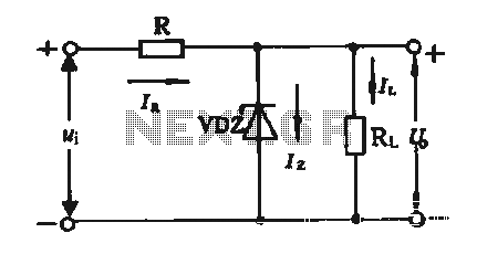
The simple voltage regulator circuit consists of a silicon regulator and a resistor. It is designed to rectify and filter DC voltage, as illustrated in the accompanying figure. The voltage regulator is connected in parallel with the load, and...
Circle i represents a two-phase grid connection line for an AC technology turbine shed, which consists of two lines. A voltage is generated between Ri through a Buck converter, with components R1 and R3 dividing the output. The sampled...
In the first circuit, the BC548 transistor is configured as a Colpitts oscillator, with the frequency being adjusted through the insertion of a crystal. A high-quality crystal will generate high-frequency oscillations, and the output at the collector is rectified...

A simple transistor amplifier circuit diagram and schematic that can be used as a 12-watt audio transistor amplifier. An operational amplifier (op-amp) integrated circuit (IC) is used to produce the required gain. This circuit is designed to amplify audio signals,...