
DC motor armature resistance in series to start debugging circuit 2

The described circuit operates a DC motor with a two-stage startup mechanism to manage inrush current and ensure smooth operation. The resistors Ri and Rz are strategically placed in series with the motor's armature to limit the initial current when the motor is powered on. This is essential for preventing damage to the motor and associated components due to high starting currents.
The control of the motor is facilitated by push-button switches, which allow the user to initiate or halt the motor's operation. When the start button is pressed, it energizes the relays KTi and KTz, which subsequently engage the startup resistors. This configuration allows the motor to ramp up to its operational speed gradually, reducing mechanical stress and electrical strain.
Once the motor reaches a certain speed, the relays automatically disengage the startup resistors, allowing the motor to operate at full efficiency. This automatic cut-in feature is crucial for optimizing performance and extending the lifespan of the motor. The use of relays in this circuit not only provides a reliable means of control but also allows for the incorporation of additional safety features, such as overload protection, depending on the specific application requirements.
Overall, the design of this DC motor control circuit exemplifies a practical approach to managing motor startup conditions, ensuring both operational efficiency and component protection. Circuit shown in Figure 3-191. The line in the DC motor armature circuit in series two-stage startup resistor Ri, Rz, Lee realized using the buttons to start and stop the motor control. During startup time by two relays KTi, KTz automatic cut in addition to two start-up resistor.
Related Circuits

A simple Frequency Shift Keying (FSK) demodulator for 2025 Hz and 2225 Hz can be designed using the LM565, a general-purpose phase-locked loop integrated circuit. This IC includes a stable, highly linear voltage-controlled oscillator that provides low distortion FM...
The circuit was designed to illustrate the use of a tone control circuit, which adjusts audio signals before they are sent to any output device. The tone control circuit serves as an essential component in audio processing systems, allowing for...

The circuit utilizes the MAX1576Y charge pump white LED driver, capable of supplying a total current of up to 480mA across two groups (n = 4 white LEDs). Each white LED in the flashing group can draw a maximum...
A second RM output and a sync input have been added to the 555 timer circuit. The sync input is derived from one of Rene Schmitz's voltage-controlled oscillators (VCOs). There are two transistors in the PCB images that lack...
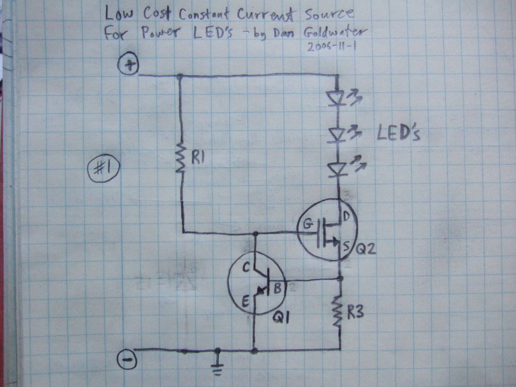
Here is a simple and inexpensive ($1) LED driver circuit. The circuit functions as a constant current source, ensuring that the LED maintains consistent brightness. The LED driver circuit is designed to provide a stable current to the LED, which...

The prototype circuit board utilized an external LCD display that received commands through an RS-232 interface. While this setup functioned adequately, programming it was cumbersome. Consequently, the circuit board was revised to support a directly attached LCD display. The...