
simplest light with constant-current LED circuit

The LED driver circuit is designed to provide a stable current to the LED, which is essential for maintaining its brightness and preventing damage due to overcurrent. The circuit typically includes a voltage source, a current-sensing resistor, and a transistor or integrated circuit that regulates the current flow.
In a basic configuration, the voltage source is connected in series with the LED and the current-sensing resistor. The resistor is placed in such a way that it allows a small portion of the current to flow through it, creating a voltage drop that can be monitored. The transistor, which acts as a switch, is connected to the resistor. When the current through the LED increases, the voltage across the resistor also increases. This change is detected by the transistor, which then adjusts its conduction state to limit the current flowing through the LED.
The choice of components is critical in determining the performance of the LED driver circuit. The current-sensing resistor should be chosen based on the desired current level for the LED, and the transistor must be capable of handling the required current without overheating. Additionally, the circuit may incorporate a heat sink to dissipate heat generated by the transistor during operation.
For applications requiring higher efficiency, a switching regulator can be utilized instead of a linear regulator. This approach minimizes power loss and maximizes the efficiency of the LED driver circuit, making it suitable for battery-operated devices.
Overall, this simple LED driver circuit exemplifies a cost-effective solution for powering LEDs while ensuring reliable operation and longevity.Here`s a really simple and inexpensive ($1) LED driver circuit. The circuit is a constant current source, which means that it keeps the LED brightne.. 🔗 External reference
Related Circuits

In most digital electronics projects that utilize various types of switches, switch bounces are frequently encountered. These are additional glitches that occur following the actual operation of the switch. These small pulses can disrupt the proper functioning of the...

A remote-operated spy robot circuit can be controlled using a wireless remote controller. It captures audio and video information from the surroundings and transmits this data to a remote station via RF signals, with a maximum range of 125...
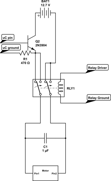
Control the state (on/off) and direction of two linear actuators that are essentially DC motors. The linear actuators operate at 12VDC and draw 10 amps of current at full load. A 25A external power supply has been purchased, as...

The circuit is designed for teaching demonstrations or experiments to hear the electrocardiogram (ECG) signal voltage. The ECG signal voltage is amplified by the LM4250 operational amplifier, which is connected to a voltage-controlled oscillator (NE566) to modulate the oscillator...
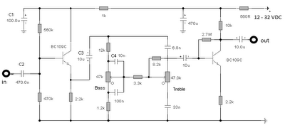
The first BC109C transistor functions as a buffer, delivering a high input impedance of approximately 250k and exhibiting a voltage gain marginally below unity. Given that the Baxendall tone control circuit operates passively, it attenuates all audio frequencies. The...

The Newman MP4 machine features three types of memory: data memory (U7), program memory (U8), and user memory (U9). Data memory is utilized for storing operational data, while program memory holds the machine's work program. User memory is designated...