
2Y- connection three two-speed motor contactor control circuits

The circuit employs a switch (SA) that allows the operator to control the motor's starting mechanism and its operational speed. When the switch is in the low-speed position, the motor operates at a reduced speed, which is particularly useful for applications requiring gradual acceleration or specific operational conditions that demand lower torque.
The time relay (KT) plays a crucial role in this circuit by providing a timed delay that facilitates the transition from low-speed operation to high-speed operation. When the switch is activated, the time relay initiates a countdown based on its preset time interval. Once this interval elapses, the relay activates, allowing the motor to receive full power and transition to high-speed operation.
This gradual increase in speed helps to protect the motor from sudden torque spikes, which can lead to mechanical stress and potential damage. Additionally, the use of a time relay allows for flexibility in adjusting the transition time, accommodating various operational needs and ensuring optimal performance of the motor in different scenarios.
Overall, this circuit design is effective for applications requiring controlled motor starting and speed regulation, enhancing both the longevity of the motor and the efficiency of the system it operates within. Circuit shown in Figure 3-98. Motor starting and low-speed operation is controlled by a switch SA. Adjust the time relay KT, the motor can be changed from low speed to start hi gh-speed operation time interval.
Related Circuits

This preamplifier is designed as a portable unit, ideal for amplifying signals generated by guitar pickups, particularly the "bug" types used with acoustic instruments. It can be utilized with any type of device and pickup. The unit features a...
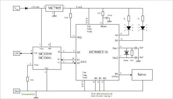
System Oscillator Crystal/Ceramic Oscillator. The following circuit combination of resistors, capacitors, and inductors depicts an equivalent circuit for a crystal or ceramic oscillator. The system oscillator, specifically a crystal or ceramic oscillator, utilizes a combination of passive components, including resistors,...
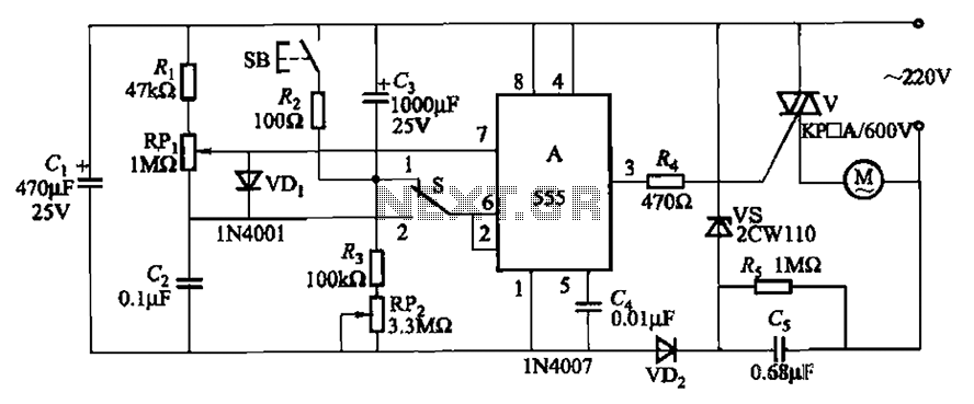
The circuit illustrated in Figure 3-12 incorporates variable speed and timing control functions. When switch S is set to position 1 and button SB is pressed, the motor initiates operation. After a predetermined delay, the motor automatically shuts down....
This circuit is designed to maintain the fluid level of a liquid between two predetermined points. It features two operational modes for either filling or emptying the container, which can be achieved by simply reversing the connections of relay...
Temperature indicators and temperature-based products have garnered significant interest due to their numerous applications and various possible solutions, each presenting unique advantages and disadvantages. This concept focuses on a sensor interface that delivers high accuracy while minimizing board space....
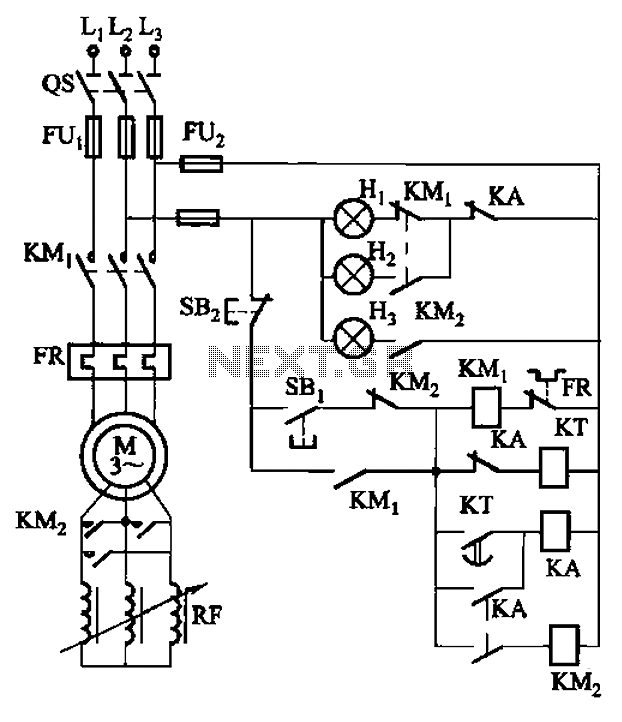
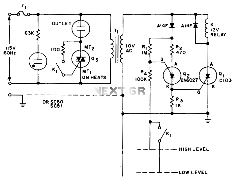
The circuit depicted in Figure 3-165 utilizes a time relay (KT) for controlling the start-up time. Indicator light Hi serves as the power indicator, H2 is designated for the start lights, and H3 functions as the running lights. The circuit...