
Three single-phase motor stepless thyristor circuits

The circuit utilizes a 555 timer IC configured in astable and monostable modes to achieve its variable speed and timing functionalities. In position 1, the 555 timer is configured in monostable mode, where pressing button SB triggers the timer. The output of the timer controls a relay or transistor that energizes the motor. The timing duration, which determines how long the motor runs before shutting off, is set by the values of the timing capacitor and potentiometer RPz. The time period can be calculated using the formula T = 1.1 * R * C, where R is the resistance in ohms and C is the capacitance in farads.
In position 2, the 555 timer is configured in astable mode, allowing it to continuously oscillate, which in turn modulates the speed of the motor. The frequency of the oscillation is determined by the resistances RPi and another fixed resistor in conjunction with a timing capacitor. By adjusting RPi, the duty cycle and frequency of the output signal can be varied, thus providing a stepless control over the motor's speed. This configuration is particularly useful in applications requiring precise speed adjustments for various operating conditions.
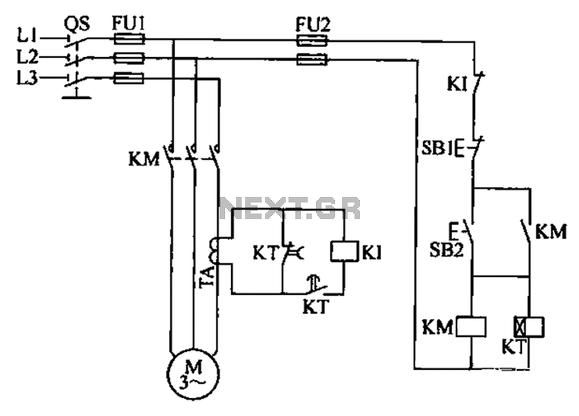
The overall design emphasizes flexibility, allowing users to tailor both the operational duration and speed of the motor to suit specific requirements. The use of a 555 timer IC simplifies the implementation of timing and speed control, making it a popular choice in many electronic applications. The circuit can be further enhanced by incorporating additional components such as diodes for flyback protection, capacitors for noise filtering, and indicators for operational status. Circuit shown in Figure 3-12. It has a variable speed and timing control functions. When the switch S placed in the 1 position, press the button SB, the motor starts running, a fter a period of delay, the motor automatically shut down, adjust the potentiometer RPz, may change the timing of time (5-60min). When S is placed Z position, the word is stepless speed circuit, adjust RPi, continuously changing the motor speed.
Mainly through 555 IC A.
Related Circuits
All electronic circuits were initially built on breadboards. Once the circuits were operational, they were soldered onto perfboards to create a more durable system. A power board was designed to stack two batteries in series, providing access to a...
A three-phase electric motor overcurrent protection circuit. This example circuit utilizes a transformer to monitor the current, ensuring that the currents in the three-phase motor do not exceed normal operating levels. When the current exceeds the set threshold, the...
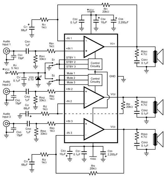
The LM4782 utilizes a protection system known as National Self Peak Instantaneous Temperature (Ke) (SPiKeTM). SPiKe safeguards the output of the LM4782 against over-voltage on the load, short circuits to ground, and provides temperature protection by monitoring instantaneous temperature....
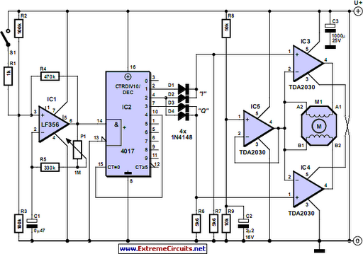
Stepper motors are offered in various versions and sizes, accommodating a range of operating voltages. This general-purpose controller supports voltages from approximately 5 V to 18 V. It can drive the motor with a peak voltage equal to half...
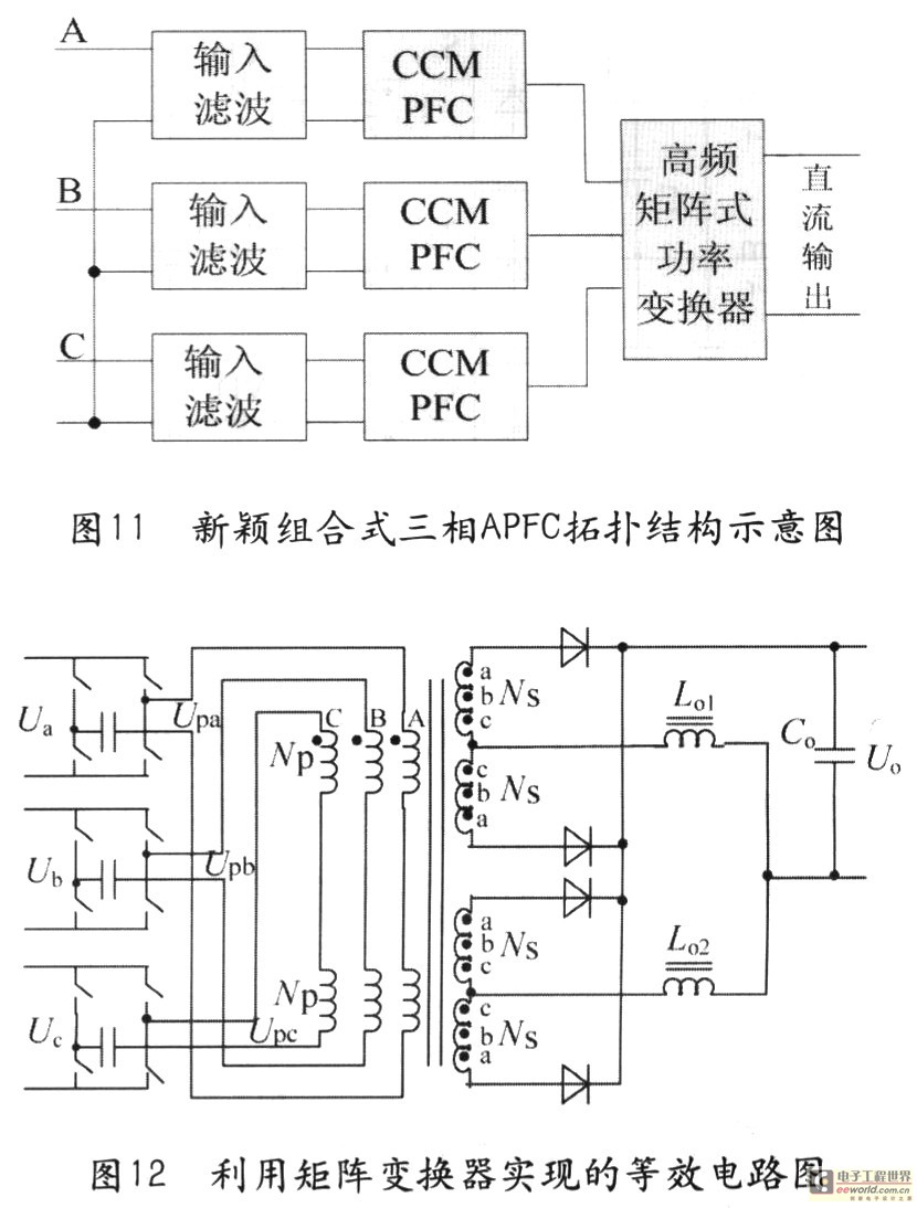
Tape isolate single-phase power factor correction (PFC) that utilizes DC/DC converters, consisting of two cables. The three-phase PFC is formed by connecting three single-phase PFCs in parallel at the output. This configuration is based on a matrix-type DC/DC converter...
In the first circuit, the BC548 transistor is configured as a Colpitts oscillator, with the frequency being adjusted through the insertion of a crystal. A high-quality crystal will generate high-frequency oscillations, and the output at the collector is rectified...